Eureka AIR delivers breakthrough ideas for toughest innovation challenges, trusted by R&D personnel around the world.

Cylinder head assembly

a technology of cylinder head and assembly, which is applied in the direction of optical radiation measurement, instruments, television systems, etc., can solve the problems of increasing the thermal load of a large number of internal combustion engine components, increasing and reducing design complexity, so as to achieve reliable temperature measurement and reduce the cost of structural measures involving more cost-effective and higher value materials. , the effect of effective cooling of the optical channel

Inactive Publication Date: 2016-10-20
DR ING H C F PORSCHE AG
View PDF9 Cites 3 Cited by
  • Summary
  • Abstract
  • Description
  • Claims
  • Application Information

AI Technical Summary

Benefits of technology

The patent describes a way to measure the temperature of an internal combustion engine's cylinder head and combustion chamber using infrared technology. This allows for precise and detailed analysis of the engine's thermal behavior in real-time operating mode. The technology uses a thermography camera to capture the infrared radiation emitted from the engine element and create an image of the temperature distribution. This method provides high accuracy and a wide temperature range, allowing for comprehensive thermal analysis of the engine.

Problems solved by technology

The thermal loading of a large number of components of the internal combustion engine also increases as a result of this increased waste heat.
In this context, structural measures involving more cost-effective and higher value materials are more expensive but generally entail lower design complexity.
Any structural change can result in changing the temperature of certain components during operation.
A disadvantage with the known method is that the temperature measuring range is small, the measuring accuracy is low and the technical complexity involved in measuring the temperature is high.
Additionally, the temperature measurement often cannot take place under real conditions, and, hence, there is a lack of certainty with respect to the measured operating temperatures.
Thus, infrared measurement can be made at difficult to access positions in the cylinder head and / or the internal combustion engine.

Method used


Image

  • Cylinder head assembly
  • Cylinder head assembly
  • Cylinder head assembly

Examples


Embodiment Construction

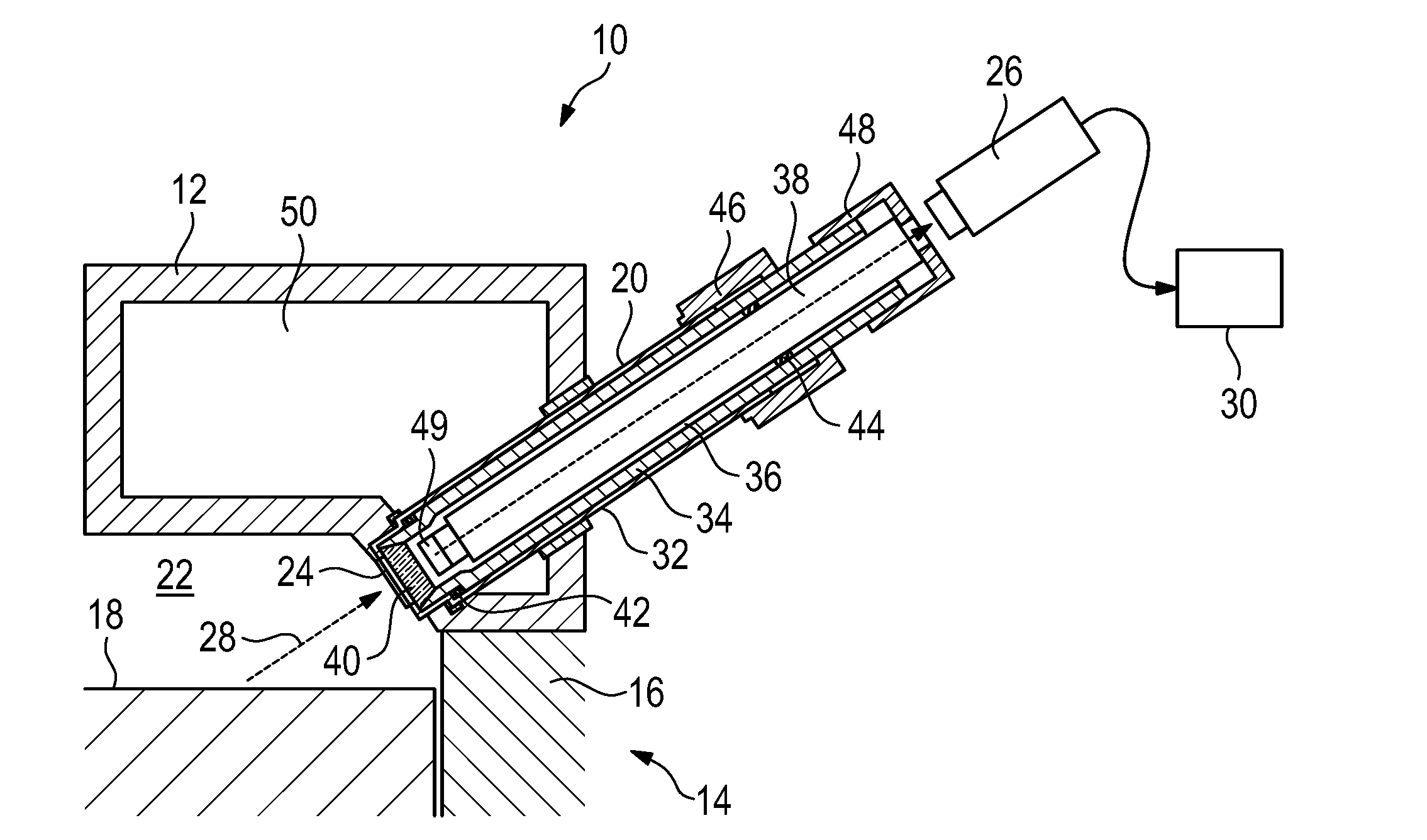
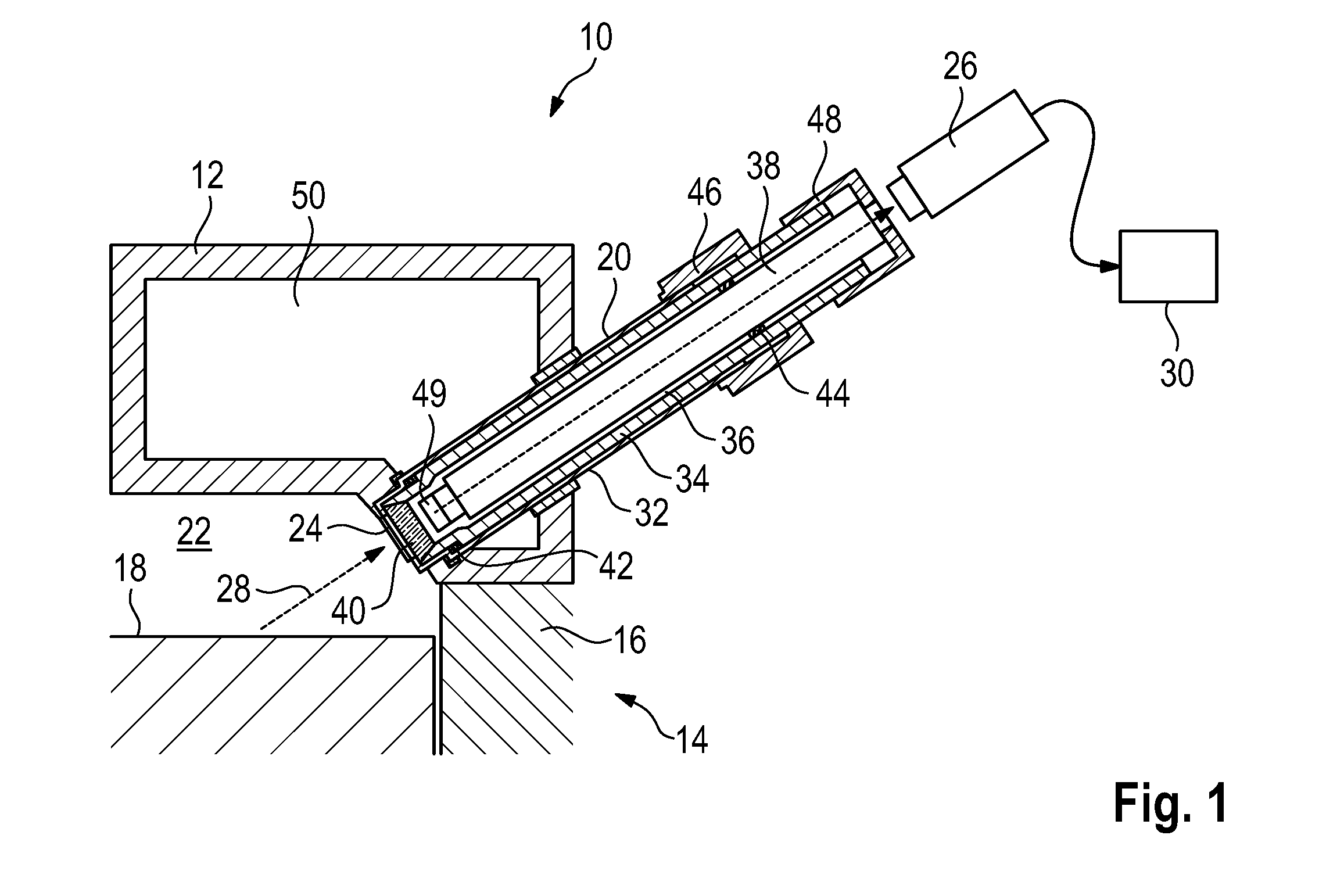
[0029]FIG. 1 illustrates a schematic partial view of a cylinder head assembly and is generally denoted by 10. The cylinder head assembly 10 has a housing 12 that delimits the cylinder head assembly 10 toward the outside. The cylinder head assembly 10 is connected to an engine block 14 that is illustrated only schematically in a partial view in FIG. 1. The engine block 14 has at least one cylinder 16 in which at least one piston 18 is accommodated. The thermal loading of the piston 18 is very high as a result of the high power densities of modern internal combustion engines. As a result, the real operating temperature of the piston and its surface have to be measured regularly during the development phase to avoid excessively high thermal loading during operation of the end.

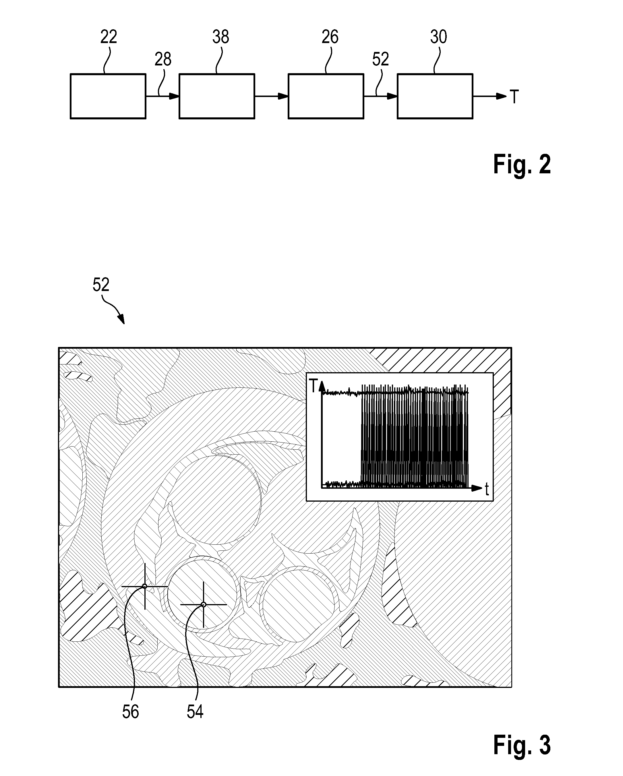
[0030]The cylinder head assembly of FIG. 1 also has an optical channel 20 formed in the housing 12 and has an opening 24 assigned to a combustion chamber 22 of the engine block 14. The optical channel 20 is connec...


PUM


Abstract

A cylinder head (10) for an internal combustion engine has a housing (12) that is assigned a multiplicity of elements (18). An optical channel (20) is formed in the housing (12) and is assigned to at least one of the elements (18). The optical channel (20) is assigned a thermography camera (26) that is designed to detect infrared radiation (28) from the at least one element (28) through the optical channel (20) to make available a thermography image (52) of the at least one element (18).

Description

CROSS REFERENCE TO RELATED APPLICATION[0001]This application claims priority under 35 USC 119 to German Patent Appl. No. 10 2015 105 920.7 filed on Apr. 17, 2015, the entire disclosure of which is incorporated herein by reference.BACKGROUND[0002]1. Field of the Invention[0003]The invention relates to a cylinder head assembly for an internal combustion engine. The cylinder head assembly has a housing with a multiplicity of elements. An optical channel is formed in the housing and is assigned to at least one of the elements. The invention also relates to a method for detecting a temperature of an element of an internal combustion engine. The invention further relates to an internal combustion engine for a motor vehicle with an engine block that has at least one cylinder and one piston.[0004]2. Description of the Related Art[0005]Legal requirements and customer demands have led to motor vehicles with lower consumption internal combustion engines that have a continuously increasing spec...

Claims


Application Information

Patent Timeline
Patent Type & Authority Applications(United States)
IPC IPC(8): H04N5/33H04N5/225G01J5/08G02B13/14G02B7/00F02F1/24G02B13/00
CPCH04N5/33F02F1/24H04N5/2252H04N5/2254G01J2005/0077G02B13/14G02B7/008G01J5/08G01J2005/0081G02B13/0095G01J5/0022H04N23/55G02B7/028G02B23/2446G02B23/2492G01J5/0818H04N23/57G01J5/48H04N23/51
Inventor FISCHER, MAXIMILIAN
Owner DR ING H C F PORSCHE AG
Why Eureka
Eureka Blog
Learn More