Hard-pressed glass light emitting diode flood lamp

a technology of light-emitting diodes and hard-pressed glass, which is applied in the direction of refractors, semiconductor devices of light sources, light and heating apparatus, etc., can solve the problems of high lumen output, high heat output of halogen lamps, and other optical qualities of par and mr halogen lamps, and achieve heat dissipation

Active Publication Date: 2015-08-11
FEIT ELECTRIC CO INC
View PDF6 Cites 16 Cited by
  • Summary
  • Abstract
  • Description
  • Claims
  • Application Information

AI Technical Summary

Benefits of technology

[0005]The following and other advantages are provided by the light emitting diode (LED) flood lamp described herein. The LED flood lamp provides a lamp with the look and lighting characteristics of a traditional parabolic aluminized reflector (PAR) or multifaceted reflector (MR) halogen lamp, but which operates more efficiently and at lower temperatures. Thus, amongst various features, the LED flood lamp disclosed herein provides a flood lamp with the design appearance of a PAR or MR halogen lamp. Additionally, the LED flood lamp disclosed herein seeks to substantially replicate the narrow beam spread and high lumen output of PAR and MR halogen lamps via a reflector configured to direct the light of the LEDs present in the LED flood lamp, a lens configured to act as an optics controller, and thus control beam spread, and / or the LED configuration within the LED flood lamp. The reflector and lens may be integrated as part of the LED flood lamp or may be a separate assembly which may, in certain embodiments, include an LED mounting surface and other components required for an operational working lamp, as will be described in further detail below. In various embodiments, the LED flood lamp may include vents to allow fluid (e.g., air, water, or the like) to pass through a portion of the LED flood lamp and assist with heat dissipation.

Problems solved by technology

Thus, halogen lamps can be dangerous.
The high heat output of halogen lamps means they are also inefficient, as a significant fraction of energy is converted to infrared radiation instead of visible radiation.
However, while successful in certain aspects, such attempts have generally failed to adequately replicate the narrow beam spread, high lumen output, and other optical qualities of PAR and MR halogen lamps.

Method used


Image

  • Hard-pressed glass light emitting diode flood lamp
  • Hard-pressed glass light emitting diode flood lamp
  • Hard-pressed glass light emitting diode flood lamp

Examples


Embodiment Construction

[0026]The present invention now will be described more fully hereinafter with reference to the accompanying drawings, in which some, but not all embodiments of the invention are shown. Indeed, this invention may be embodied in many different forms and should not be construed as limited to the embodiments set forth herein; rather, these embodiments are provided so that this disclosure will satisfy applicable legal requirements. Like numbers refer to like elements throughout.

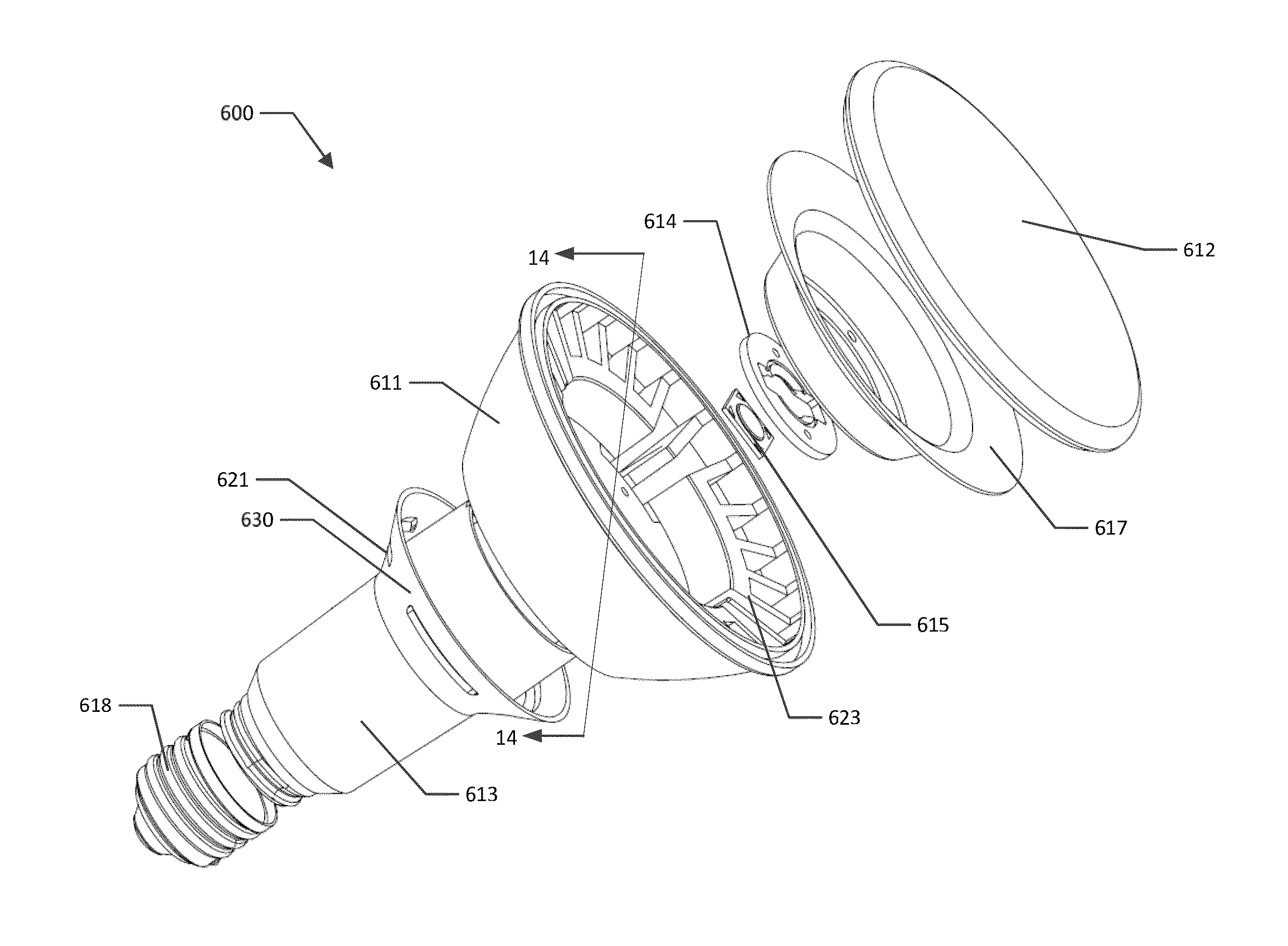
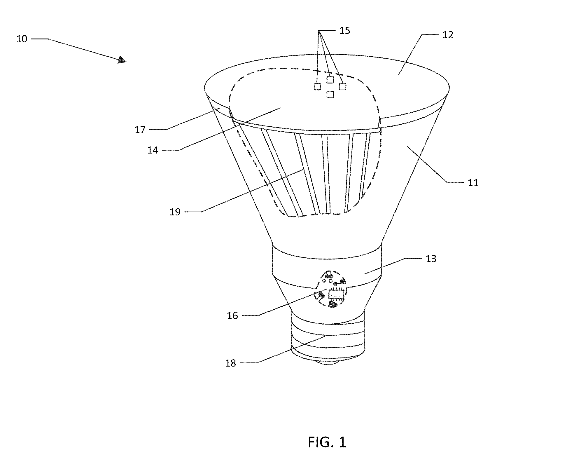
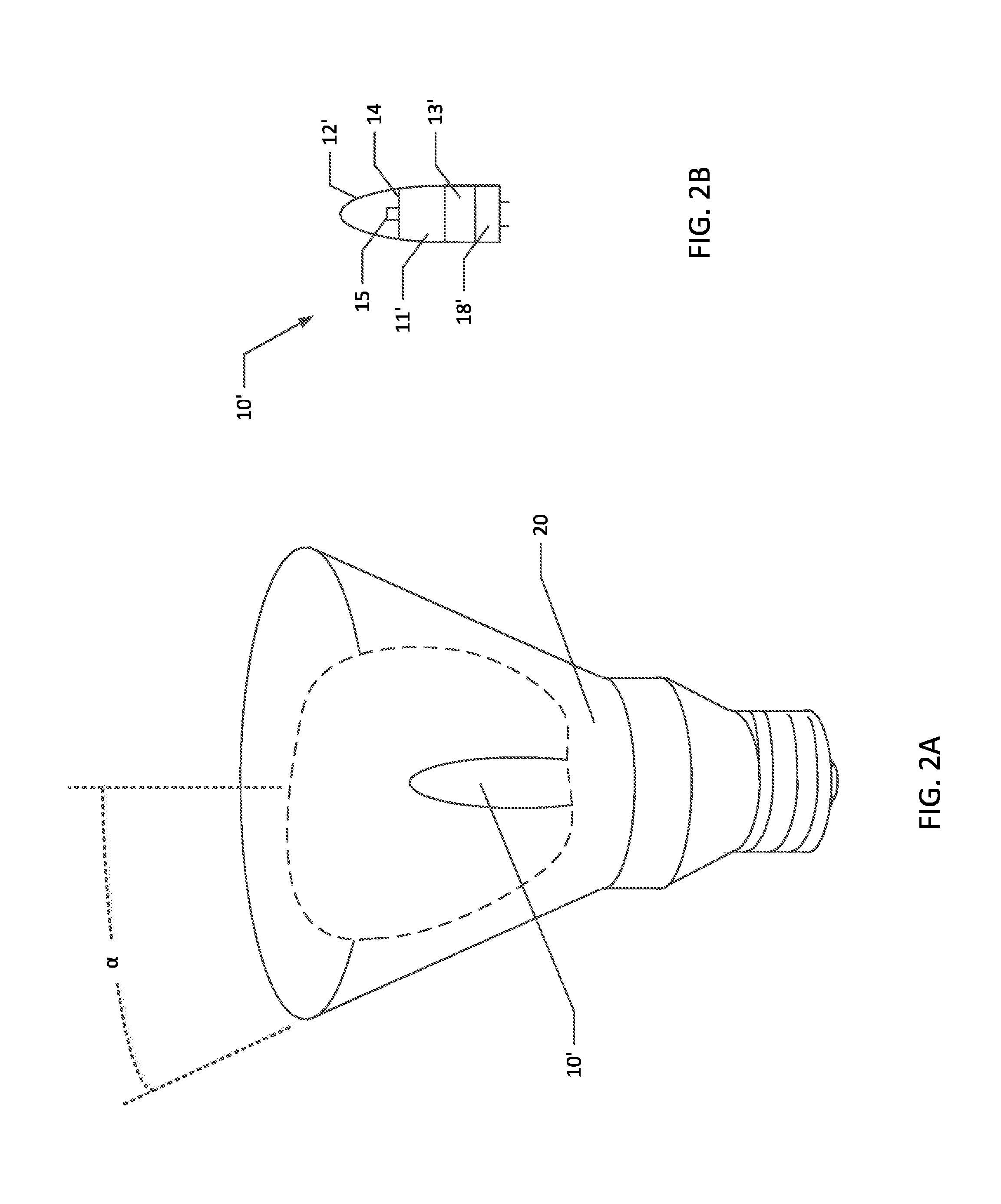
[0027]As shown in FIG. 1, a first exemplary LED flood lamp 10 may according to various embodiments comprise a base cap 18, a first housing 13, a second housing 11, a reflector 17, and a lens 12. In certain embodiments, the LED flood lamp 10 may also comprise an LED mounting surface 14, upon which at least one LED 15 may be mounted. In some embodiments, the LED flood lamp 10 may further comprise driver circuitry 16. In some embodiments, the LED flood lamp 10 may comprise a heat sink 19. In still other embodiments, ...


PUM


Abstract

In various embodiments, a light emitting diode (LED) flood lamp is provided. The LED flood lamp may include a base cap; a first housing having a first end and a second end, the first end secured to the base cap; a second housing having at least in part a partially conical shape, an end of the second housing having a smaller diameter secured to the second end of the first housing; at least one LED secured within the second; driver circuitry secured within the LED flood lamp between the end of the base cap and the at least one LED; a reflector having a partially conical shape; and a diffuser element secured to at least one of a wider end of the reflector or the end of the second housing having the larger diameter. In some embodiments, the first or second housing may include one or more vents.

Description

CROSS-REFERENCE TO RELATED APPLICATIONS[0001]This application claims priority to U.S. Provisional Application Ser. No. 61 / 826,609, filed May 23, 2013, and U.S. Provisional Application Ser. No. 61 / 863,063 filed Aug. 7, 2013, the contents of both of which are incorporated by reference herein in their entireties.BACKGROUND[0002]Conventional parabolic aluminized reflector (PAR) and multi-faceted reflector (MR) halogen lamps, also known as flood lamps, are used in a variety of contexts because of their white light (generally 2800-3200 K) and narrow beam spread (generally 8-60 degrees). However, halogen lamps operate at high temperatures and are capable of reaching temperatures of 260° C. (500° F.) or more during operation. Thus, halogen lamps can be dangerous. The high heat output of halogen lamps means they are also inefficient, as a significant fraction of energy is converted to infrared radiation instead of visible radiation. In order to help protect against lamp breakage due to the h...

Claims


Application Information

Patent Timeline
Patent Type & Authority Patents(United States)
IPC IPC(8): F21K99/00
CPCF21K9/1375F21K9/90F21K9/23F21V5/048F21V29/777F21V7/06F21V7/048F21V13/04F21V19/0065F21V29/83F21V23/009F21V23/06
Inventor FEIT, ALAN BARRY
Owner FEIT ELECTRIC CO INC
Why Eureka
Try Eureka