Archery sight

a sight and archery technology, applied in the field of sighting devices, can solve the problems of cant (or deviation of the bow limbs from a common vertical plane), and is generally undesirabl

Inactive Publication Date: 2015-08-11
LARSON ARCHERY
View PDF15 Cites 7 Cited by
  • Summary
  • Abstract
  • Description
  • Claims
  • Application Information

AI Technical Summary

Benefits of technology

[0010]It is generally desirable for a bow to be sighted-in, and shot, while disposed in a repeatable vertical orientation. That is, cant (or deviation of the bow limbs from a common vertical plane), is generally undesirable. Sometimes, embodiments of a sight according to certain principles of the invention may include cant-indicating structure to provide feedback to an archer during aim of a bow on which the sight is affixed. One operable cant-indicating structure includes a bubble level. Preferably, the bubble level is disposed inside the perimeter of the guard. One aspect sometimes provided by a single “fixed” pin, is that the other pins may be operably distributed within the limited area confined within the guard, without visually or structurally interfering with the bubble level.
[0011]For example, it is within contemplation that a pin associated with a “longest shot” may be “fixed”, with respect to a guard perimeter, at a desirable and workable location near a bubble level. That “longest shot” pin can then be sighted-in, and the guard will be positioned accordingly. All other sight pins can then be individually adjusted with respect to the guard perimeter, as required, to locate each pin's aim point in correspondence with the arrow strike location at a desired closer target range. Consequently, the collection of sight pins may be automatically and optimally spread out inside the perimeter of the guard.

Problems solved by technology

That is, cant (or deviation of the bow limbs from a common vertical plane), is generally undesirable.

Method used


Image

  • Archery sight
  • Archery sight
  • Archery sight

Examples


Embodiment Construction

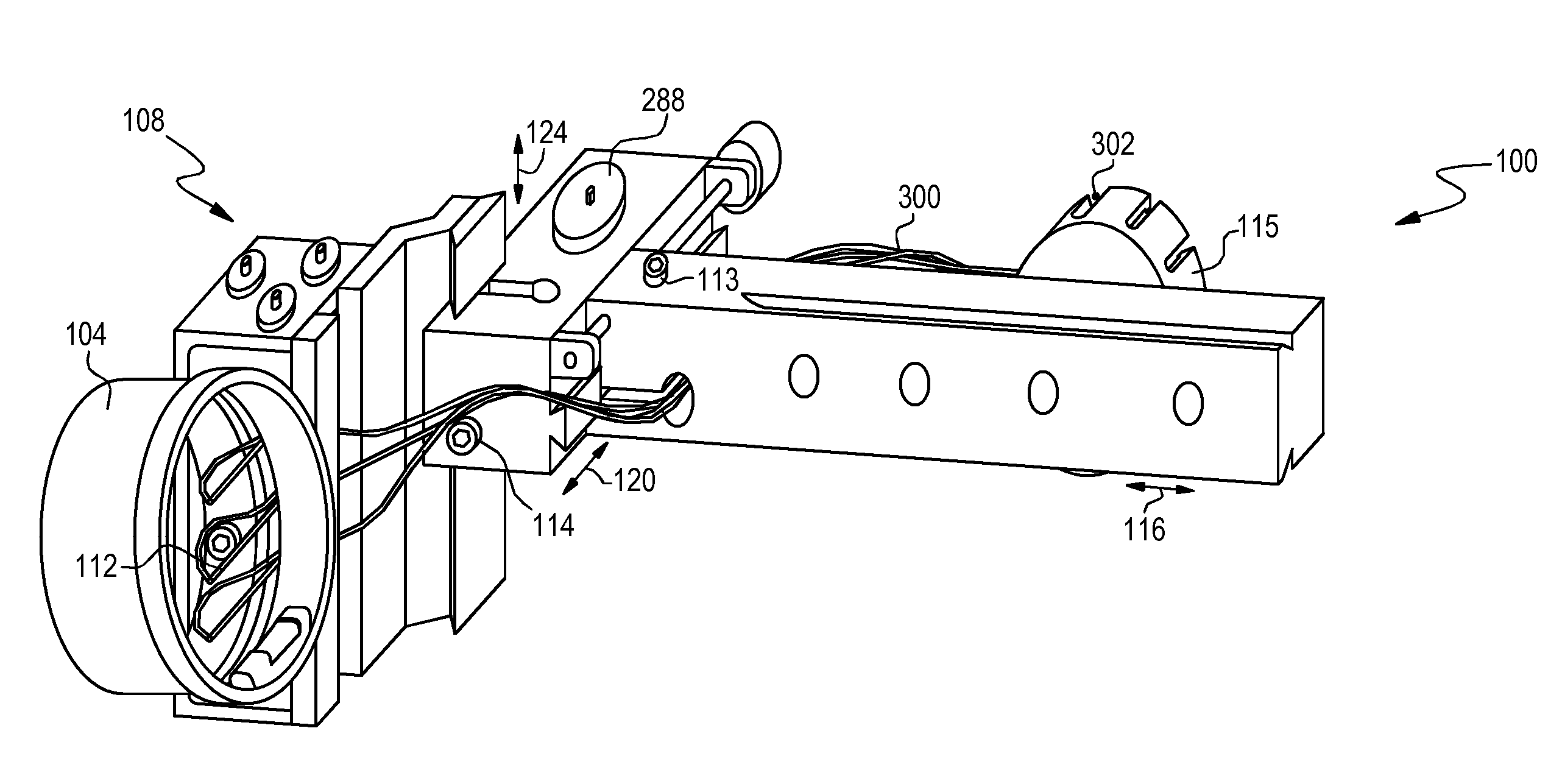
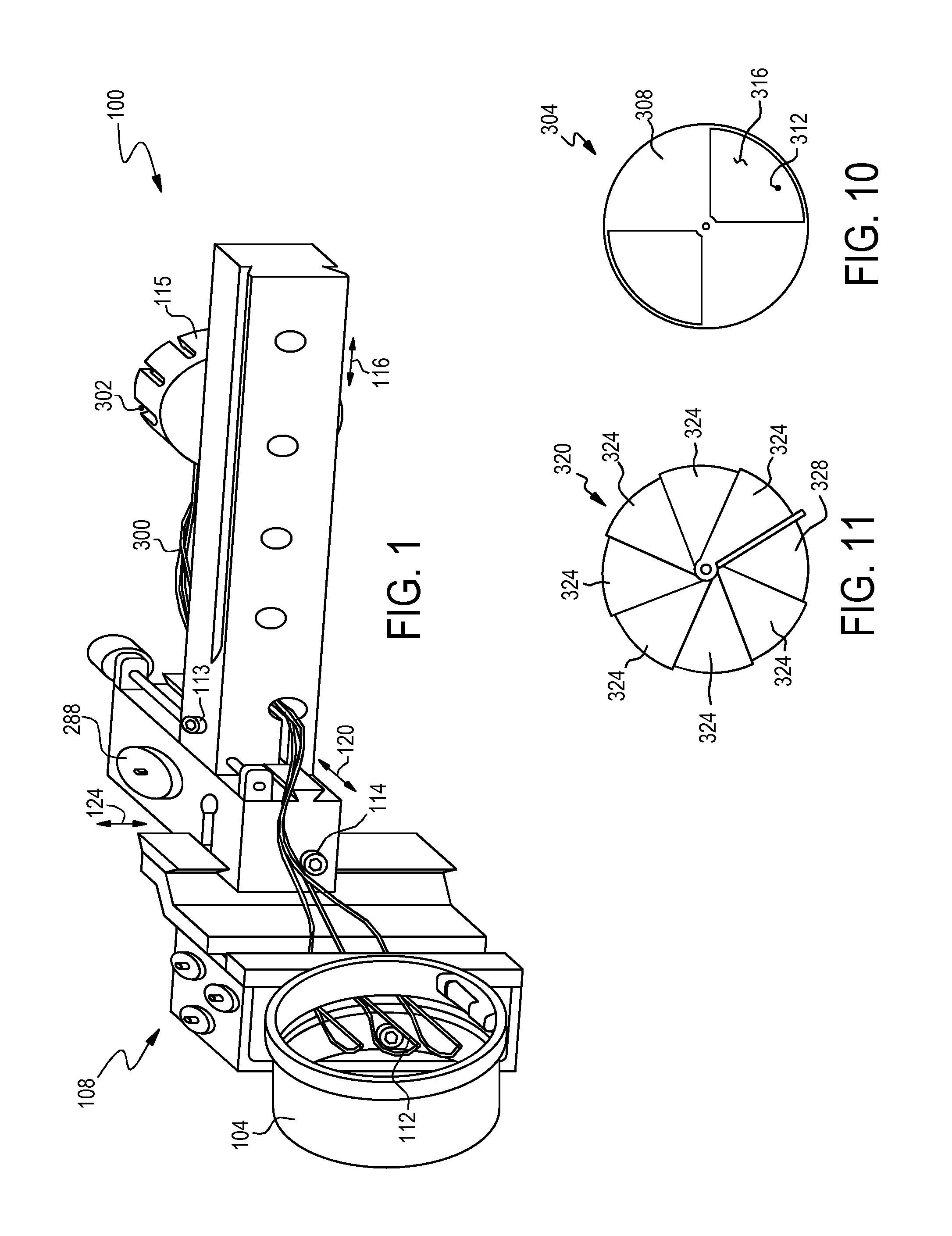
[0022]FIG. 1 is a view in perspective of a currently preferred embodiment;

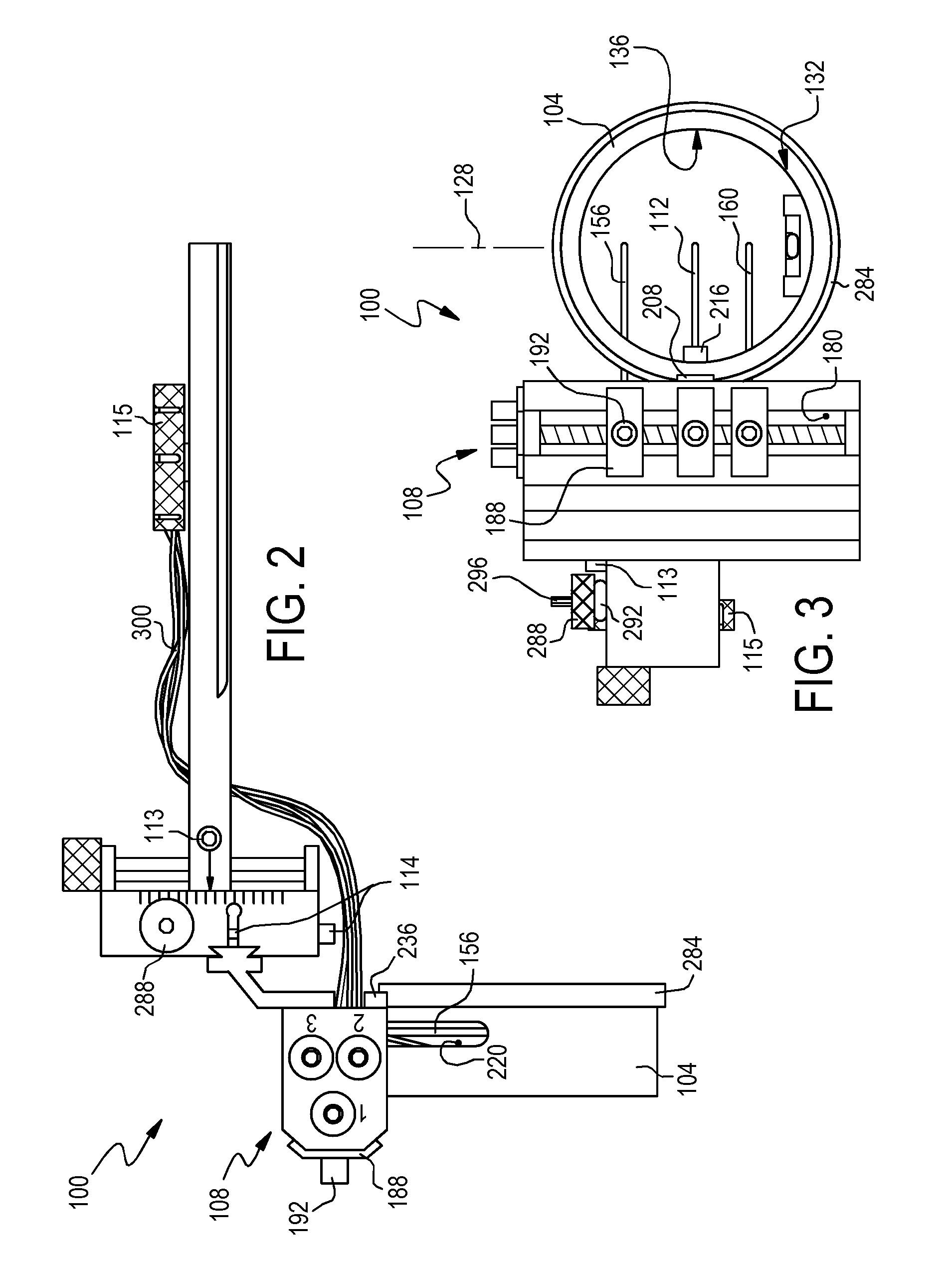
[0023]FIG. 2 is a top view of the embodiment in FIG. 1;

[0024]FIG. 3 is a front end view of the embodiment in FIG. 1;

[0025]FIG. 4 is a left side view of the embodiment in FIG. 1, with the fiber optic elements removed;

[0026]FIG. 5 is an exploded right side view of a workable guard for the embodiment in FIG. 1, and including certain optional elements;

[0027]FIG. 6 is a right side view of the cage portion of the embodiment in FIG. 1;

[0028]FIG. 7 is an exploded front end view of a portion of the embodiment in FIG. 1;

[0029]FIG. 8 is an exploded assembly front view (rotated CCW 90 degrees) of pin arms of the embodiment in FIG. 1;

[0030]FIG. 9 is a top view of a portion of the central pin arm in FIG. 8;

[0031]FIG. 10 is a right side view of an optional light-blocking cover; and

[0032]FIG. 11 is a right side vice of an alternative light-blocking cover.

DETAILED DESCRIPTION OF THE ILLUSTRATED EMBODIMENTS

[0033]Reference will ...


PUM


Abstract

An archery sight with a plurality of sight pins and a perimeter guard essentially surrounding the pins. The sight can be structured such that a first sight pin is disposed at a fixed position, relative to the guard, at a plurality of sight-in distance configurations for the first sight pin. In that case, the position of at least a second sight pin is changed, relative to the guard, as a sight-in distance configuration is changed for the first sight pin. Sights may provide visual cant and/or yaw feedback for an archer. Some guards may be partially or virtually enclosed to resist damage to sight pins or other internal mechanisms, and may provide visual magnification.

Description

BACKGROUND[0001]1. Field of the Invention[0002]This invention relates to sighting devices for ballistic projectiles. It is particularly directed to a sight adapted for use in the field of archery.[0003]2. State of the Art[0004]Pin sights are in extensive use by archery hunters. Several versions have evolved over the years, in response to the changing demands of the marketplace. A principal driving force for pin sight development has been the advancing technology of the archery bows, with which those sights are used.[0005]A traditional fixed-pin sight usually has 3 to 5 pins, which can be individually set for a particular known distance (yardage). The top pin establishes a selected yardage distance, and progressively lower pins establish correspondingly longer distances. Once set, the pins are tightened and remain “fixed” in position during use. Setting up and adjusting a fixed-pin sight is relatively straight forward, but requires some trial and error testing.[0006]Typically, the gr...

Claims


Application Information

Patent Timeline
Patent Type & Authority Patents(United States)
IPC IPC(8): F41G1/467
CPCF41G1/467F41G1/345F41G1/383
Inventor LARSON, MARLOW W.
Owner LARSON ARCHERY
Why Eureka
Try Eureka