
Crank arm spider improvement for attaching ovoid chainrings

a technology of ovoid chainrings and spiders, which is applied in the direction of chain/belt transmission, mechanical equipment, transportation and packaging, etc., can solve the problem of solving a minimum 3° structural limitation, and achieve the improvement of the biomechanics of pedaling, the effect of reducing the angular increment and multiplying the number of different chainring angular positions

Inactive Publication Date: 2015-08-18
ROTOR COMPONENTES TECHCOS
View PDF9 Cites 3 Cited by
  • Summary
  • Abstract
  • Description
  • Claims
  • Application Information

AI Technical Summary

Benefits of technology

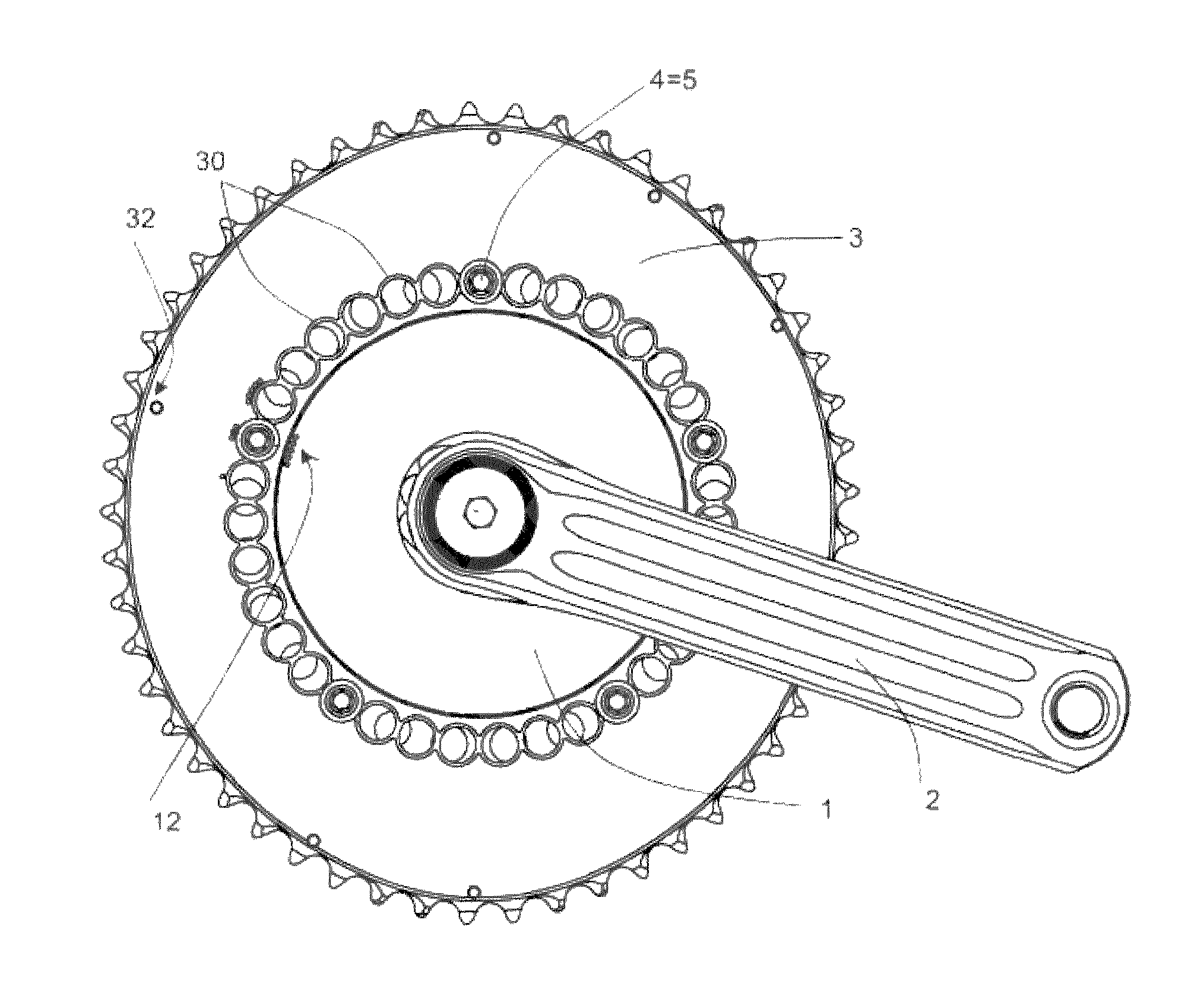
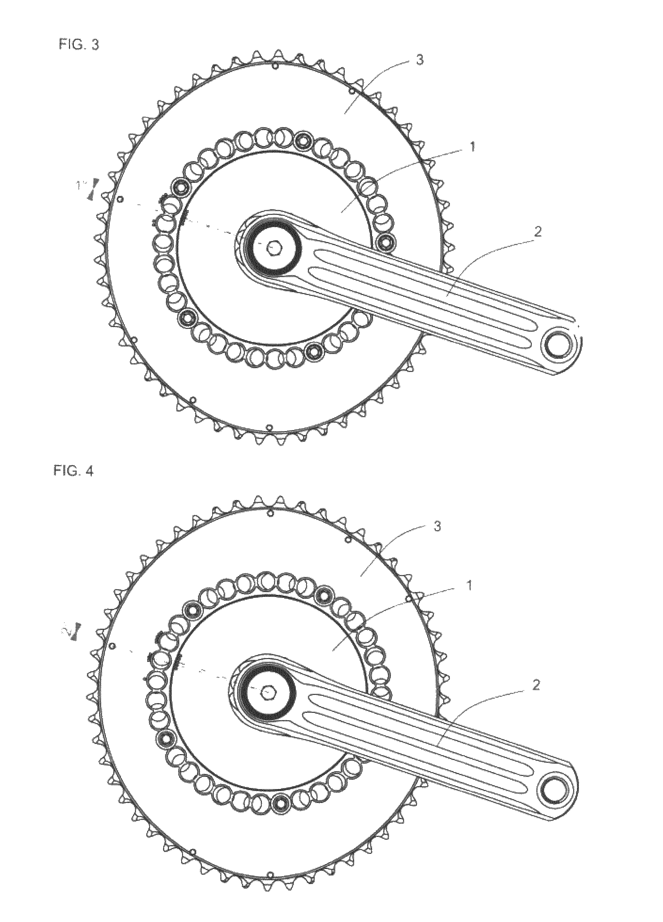
[0016]Therefore, the present application provides a solution to this technical problem providing a more accurate adjustment orientation system in order to complement the divisions of a main scale arranged in an ovoid chainring via the chainring anchorage points, combining it with a second auxiliary scale arranged in the spider via the spider anchorage points which is able to rotate relative to the main scale thus multiplying the number of different chainring angular positions and reducing the angular increment between consecutive chainring's (3) orientations below 3°.
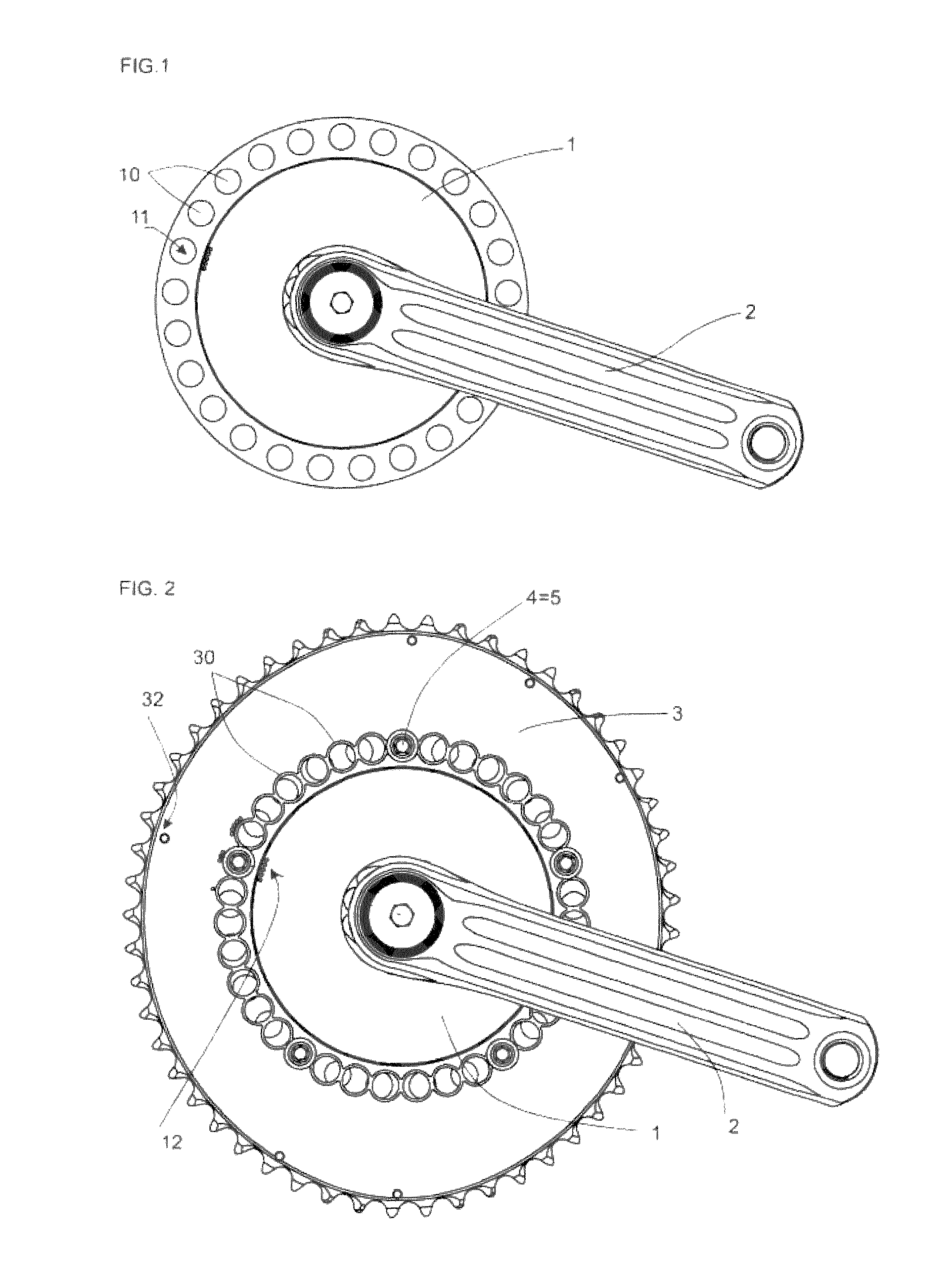
[0018]To this end, we propose a crank arm spider which may be either removable or not from the drive-side crank arm. Said spider is provided with a multiplicity of spider anchorage points for attaching chainrings, being the number of said spider anchorage points multiple of the number of the mentioned mechanical anchorage means, thus allowing different orientations when it incorporates ovoid chainrings.
[0021]The present invention discloses different possibilities: firstly, it provides a crank arm spider adjustment orientation system for usual ovoid chainrings which lack of their own orientation adjustment means; and secondly, we get a major advantage by combining this spider solution with ovoid chainrings provided themselves with an adjustment orientation system, multiplying the resulting orientations, avoiding the structural restrictions and providing a chainring angular orientation ranging small increments for allowing the users to always find a satisfactory individual orientation. So, with this disclosed arrangement we can achieve all desired orientations, from the point of view of the biomechanical performance, in sport or even scientific research level.

Problems solved by technology

It is known a main scale fixing angular orientation increments by using multiple anchorage points arranged on the ovoid chainring itself (disclosed in documents from the same applicant EP1863699 and EP2595869) in order to provide an ovoid chainring with different orientation settings (varying the angle existing between the major axis of said ovoid chainring and the plane containing both crank arms), but this solution has a structural limitation of minimum 3° because this angular increment is limited by the distance between axes of the holes made in the chainring.
However, the solution consisting of further approaching the consecutive holes to decrease said angular increment by overlapping holes, does not meet the resistance and rigidity features required in the anchorage points between chainring and crank arm spider for transmitting power, because these holes must be sufficiently separated so that between them there is enough material to guarantee the tangential attachment in order to bear its corresponding mechanical anchorage means, so working under load, these means does not slide to the adjoining hole by breaking or deforming the material.

Method used


Image

  • Crank arm spider improvement for attaching ovoid chainrings
  • Crank arm spider improvement for attaching ovoid chainrings
  • Crank arm spider improvement for attaching ovoid chainrings

Examples


Embodiment Construction

[0040]Referring to a crank arm spider, it is proposed a crank arm spider adjustment orientation system to provide different angular orientations in the attachment of at least one ovoid chainring, consisting of, at least an ovoid chainring (3) having a major diameter, whose angle with a crank arm (2) measured in the pedaling direction defines its orientation, and provided with a number of chainring anchorage points (30) arranged as holes distributed along the perimeter corresponding to a chainring bolt circle diameter in order to attach the ovoid chainring (3) to a crank arm (2) in a plurality of angular orientations; a spider (1) coupled to said crank arm (2), provided with a plurality of spider anchorage points (10) arranged as holes distributed along the perimeter corresponding to a spider bolt circle diameter in order to attach the ovoid chainring (3) in a plurality of angular orientations; and mechanical anchorage means (5), usually screws and nuts, in order to make integral sai...


PUM


Abstract

Crank arm spider adjustment orientation system to provide different angular orientations in the attachment of at least an ovoid chainring, comprising an ovoid chainring (3) and a spider (1), both of them provided with multiple anchorage points (30, 10) arranged as holes distributed along the perimeter of a BCD, and mechanical anchorage means (5) engaging chainring anchorage points (30) with corresponding spider anchorage points (10); where the number of said spider anchorage points (10) is multiple of and greater than the number of said mechanical anchorage means (5), and the angular increment between consecutive chainring's (3) orientations provided by the chainring anchorage points (30) is different than the angular increment between consecutive chainring's (3) orientations provided by the spider anchorage points (10), so the combination of the spider (1) with at least one ovoid chainring (3) multiplies the possibilities for said ovoid chainring's (3) orientation reducing the angular increment between consecutive chainring's (3) orientations.

Description

[0001]The present invention relates to a bicycle crank arm capable to attach in different angular positions to non-circular chainrings, in which the orientation or relative position between a major chainring diameter and the crank arm direction is a fundamental parameter in the optimization of pedaling biomechanics.PRIOR ART[0002]The crankset is the component of a bicycle drivetrain that converts the reciprocating motion of the rider's legs into rotational motion used to drive the chain, which in turn drives the (usually) rear wheel. It comprises one or more chainrings attached by means of a spider to one of the two crank arms, to which the pedals attach. This crankset is connected to the rider by the pedals, to the bicycle frame by the bottom bracket bearings, and to the rear sprocket, cassette or freewheel via the chain.[0003]The two crank arms, one on each side and usually mounted 180° out of phase, connect the bottom bracket axle to the pedals. And the spider is usually a multi-...

Claims


Application Information

Patent Timeline
Patent Type & Authority Patents(United States)
IPC IPC(8): B62M3/00B62M9/02B62M3/16B62M9/08B62M9/00
CPCB62M3/16B62M9/00B62M9/02B62M9/08B62M2009/002Y10T74/2165
Inventor CARRASCO VERGARA, PABLO
Owner ROTOR COMPONENTES TECHCOS
Learn More