Contactless switches

a technology of contactless switches and switches, which is applied in the direction of mechanical control devices, instruments, pulse techniques, etc., can solve the problems of reducing the reliability of devices in the long term, affecting the operation efficiency of devices, etc., and achieves the effect of convenient operation modifications and great flexibility

Inactive Publication Date: 2008-11-20
DELPHI TECH INC
View PDF10 Cites 0 Cited by
  • Summary
  • Abstract
  • Description
  • Claims
  • Application Information

AI Technical Summary

Benefits of technology

[0026]All these contactless solutions meet new requirements expressed for example by motor vehicle constructors relating to the reliability and lifetime of the components used. They also allow application of switching solutions in contexts in which constraints are very tight.
[0027]Lastly, they offer great flexibility in that on-demand programming of the detected codes, by means of micro-controllers processing the detected signals, allows easy operational modifications since only the program has to be changed. Moreover, the software basis of the switches allows the number of functions demanded to be multiplied.

Problems solved by technology

Consequently, there is always a physical link between the elements, which link causes a certain wear and reduces the reliability of the devices in the long term.

Method used


Image

  • Contactless switches
  • Contactless switches
  • Contactless switches

Examples


Embodiment Construction

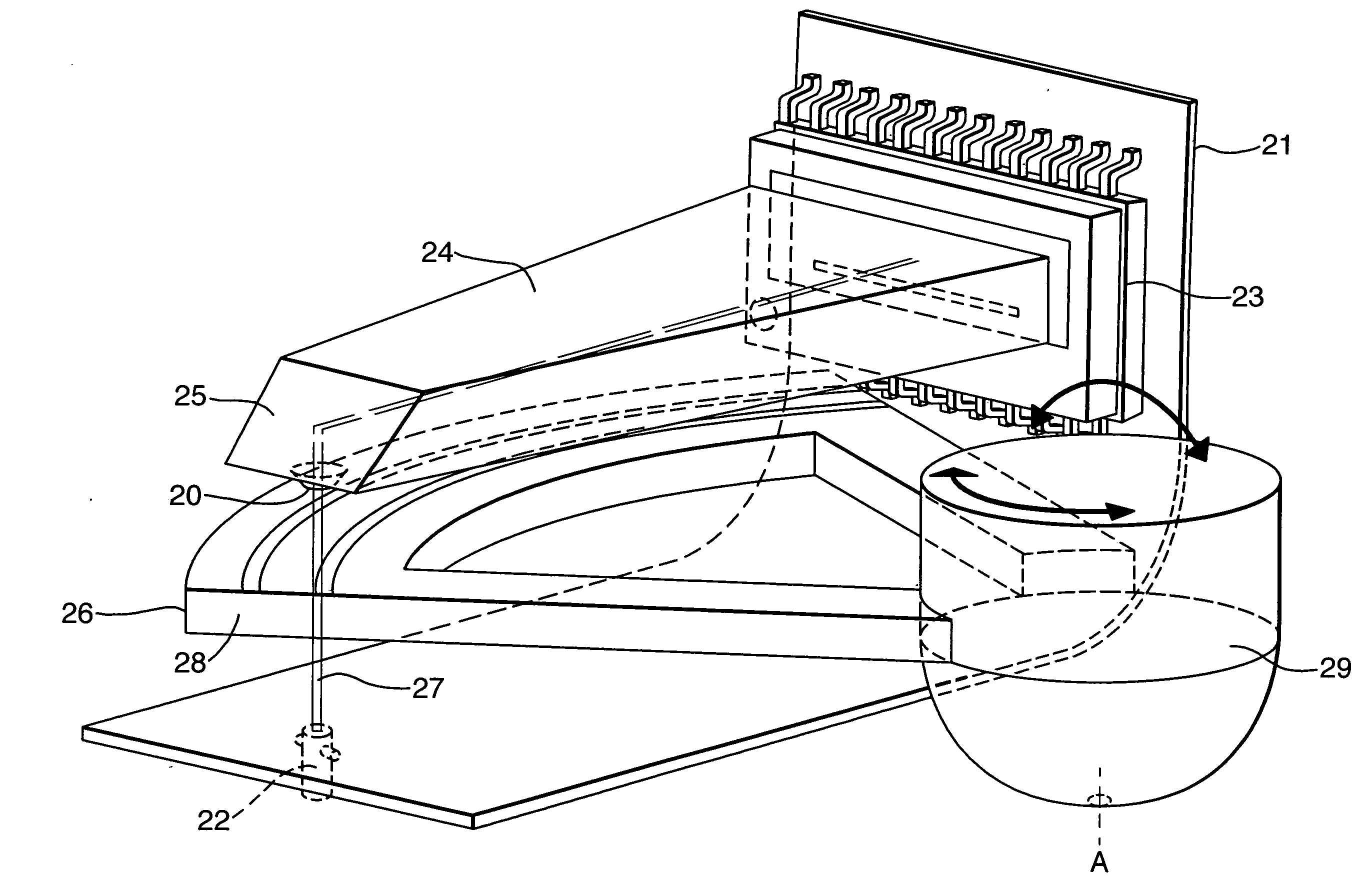
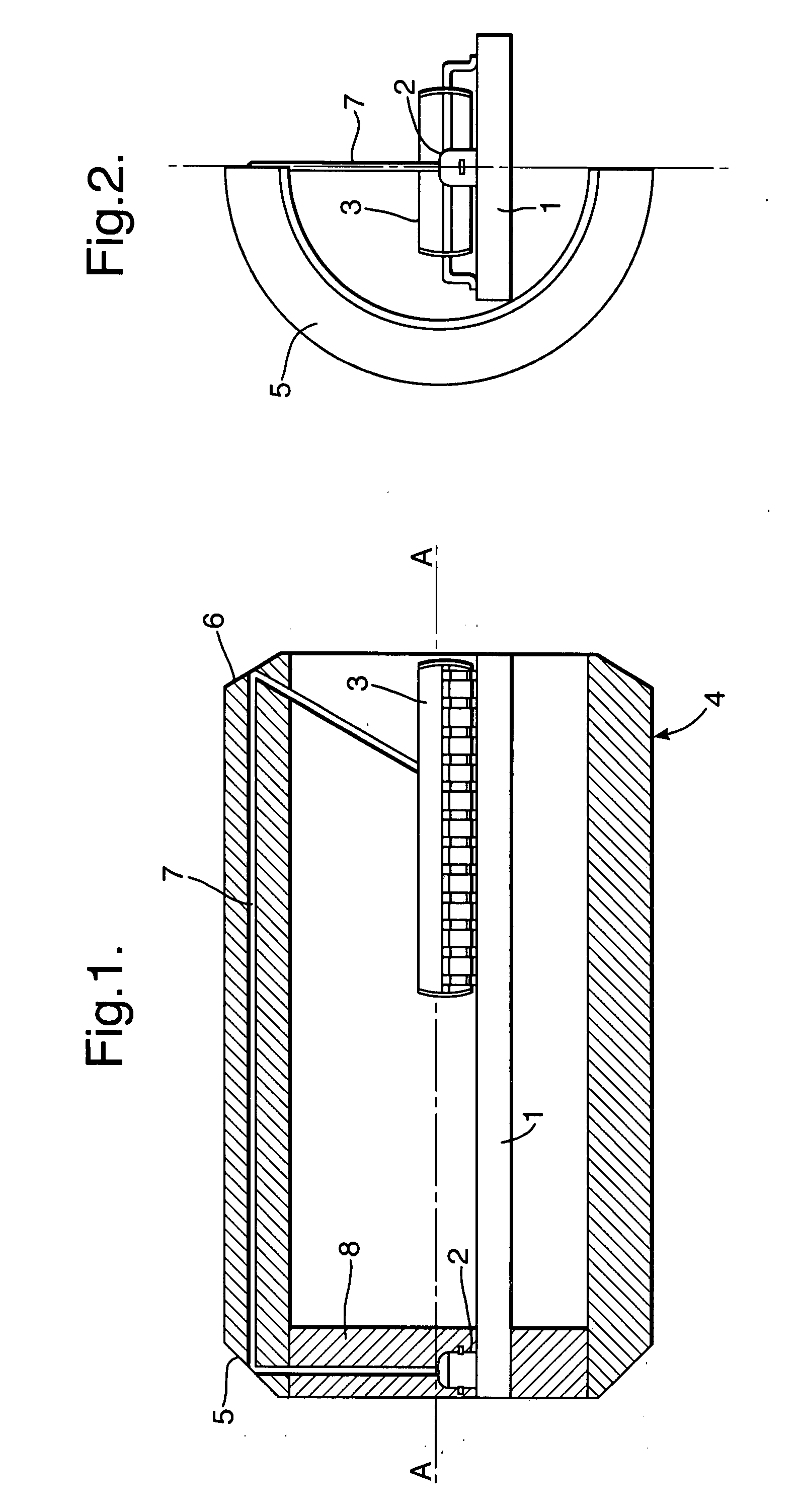
[0034]With reference to FIG. 1, the fixed part is formed of a support (1) of printed circuit type on which are arranged on the one hand a laser diode (2) and on the other a photodetector (3). The rotary casing (4) includes two bevelled ends (5) and (6) reflecting light. The laser beam (7) emitted by the diodes (2) perpendicularly to the axis of rotation (A) is emitted, due to the positioning of the laser diode (2), towards the reflective surface (5), which is orientated at 45° so that the said beam (7) is then returned parallel with the axis of rotation (A) towards the other reflective surface (6), and then reflected towards the photodetector (3).

[0035]Before reflection on the reflective surface (5), the laser beam passes through an annular zone (8) covered with a track of computer-generated holograms combined with diffractive lenses. The diffracted laser beam (7) contains data relating to the instantaneous position of the ring (4) relative to the fixed support, in this case the pri...


PUM


Abstract

Switch including a support control organ in motion relative to a fixed device, the organ and the support being in such a relationship that a plurality of distinct relative positions produce differentiatable data producing different effects. One of the organ or the support includes at least one laser diode emitting a light beam and at least one photodetector, the other including a least one zone situated in the path of the laser beam and provided with computer-generated holograms forming elementary coding cells in order to perform spatial coding of the relative organ/support position. The beam sent by the laser diode is diffracted by the holograms in order to form a binary optical code which can be read by the photodetector and directly and instantaneously transformed into a binary electronic code.

Description

TECHNICAL FIELD[0001]The present invention relates to a contactless switch conventionally including a control organ in movement relative to a fixed support, the organ and the support being in such a relationship that a plurality of distinct relative positions generate differentiatable data producing different effects.BACKGROUND OF THE INVENTION[0002]At the present time, switching or controlling are generally performed by means of levers or buttons, which actuate slides, contacts, or rollers. This is, for example, the case in steering wheel controls of motor vehicles. Consequently, there is always a physical link between the elements, which link causes a certain wear and reduces the reliability of the devices in the long term.SUMMARY OF THE INVENTION[0003]The aim of the present invention is to remedy these disadvantages.[0004]The switch of the invention therefore proposes a solution which dispenses with all physical contact and is principally characterised by the fact that one of the...

Claims


Application Information

Patent Timeline
Patent Type & Authority Applications(United States)
IPC IPC(8): H03K17/78G02B5/32
CPCG01D5/26G01D5/347G01D5/34784G05G2009/04759G01D2205/90
Inventor TUPINIER, LARUENTMARROUX, OLIVIER R.
Owner DELPHI TECH INC
Why Eureka
Try Eureka