Installation comprising seabed-to-surface connections of the multi-riser hybrid tower type, including positive-buoyancy flexible pipes

a technology of flexible pipes and hybrid towers, which is applied in the direction of drilling pipes, drilling casings, borehole/well accessories, etc., can solve the problems of flexible pipes running the risk of interfering with one another, difficult to fabricate, and high cost of such a multitude of flexible pipes

Active Publication Date: 2015-08-25
SAIPEM SA
View PDF29 Cites 8 Cited by
  • Summary
  • Abstract
  • Description
  • Claims
  • Application Information

AI Technical Summary

Benefits of technology

[0075]Another advantage of the present invention lies in that because of this small angular variation of the top end of the vertical riser, it is possible at its bottom end to make use of its foot being rigidly embedded in a second or nth base resting on the sea bottom without having recourse to an inertia-transition part of size that is too great, which would therefore be too expensive. It is also possible to avoid using a flexible hinge, in particular of the flexible ball-joint type, providing the junction between the bottom end of the second or nth riser and said embedded end includes an inertia-transition part.
[0076]Likewise, and in known manner, it can be understood that said top carrier structure serves to keep the top ends of said risers and of said vertical tension leg in an unvarying geometrical configuration ensuring that they are fixed to one another at a constant distance.
[0077]In known manner, said turret includes a cavity within a structure that is offset in front of the floating support or that is incorporated in or under the hull of the floating support, said cavity preferably passing through the full height of the hull of the floating support.
[0078]Also in known manner, said vertical tension leg is constituted by a cable or by a rigid bar, in particular made of metal, or indeed by a pipe.
[0079]In known manner, said terminal portion of the first flexible pipe extends over a fraction only of the total length of the first flexible pipe such that said first flexible pipe presents an S-shaped configuration, with a first portion of the first flexible pipe beside said floating support presenting concave curvature in the form of a dipping catenary, and said remaining terminal portion of said first flexible pipe presenting convex curvature in the from of an upside-down catenary because of its positive buoyancy. The term “concave curvature” is used herein to mean that said first portion of the first flexible pipe has curvature with its concave side facing upwards, and the term “convex curvature” is used to mean that said terminal portion of the first flexible pipe has curvature with its convex side facing upwards or its concave side facing downwards.
[0080]It can be understood that said first and second flexible pipes positioned at different heights means that two points respectively of an upper first one of the first flexible pipes and of a lower second one of the first flexible pipes situated in a common vertical direction are always situated one above the other, even though a point of the upper flexible pipe may be lower than a point of the lower flexible pipe, providing the two points of the upper and lower first flexible pipes are not in vertical alignment.

Problems solved by technology

Nevertheless, with that type of bottom-to-surface connection between the turret of a floating support and pipes resting on the sea bottom, it is not possible to use said flexible pipes in a dipping catenary configuration, i.e. with a low point of inflection as described for hybrid tower type bottom-to-surface connections that comprise:a vertical riser having its bottom end anchored to the sea bottom via a flexible hinge and connected to a said pipe resting on the sea bottom, and having its top end connected to a float immersed in the subsurface and serving to tension the riser; anda connecting flexible pipe between the top end of said riser and a floating support on the surface, said connecting flexible pipe possibly taking up under the effect of its own weight the shape of a dipping catenary curve, i.e. a curve that goes down well below the float and subsequently rises up to said floating support, which dipping catenary is capable of accommodating large amounts of movement of the floating support, with this being absorbed by deformation of the flexible pipe, in particular by raising or lowering said low point of inflection of the dipping catenary.
However, as soon as the water reaches a depth lying in the range 1000 m to 1500 m, or indeed 2000 m to 3000 m, the cost of such a multitude of flexible pipes becomes very high because of the developed length of each of said flexible pipes, since such flexible pipes are very complex and very difficult to fabricate if they are to achieve the levels of safety in operation that are required to enable them to remain in operation over periods of time that may reach or exceed 20 years to 25 years, or even more.
In particular, the flexible pipes run the risk of interfering with one another and striking against one another.

Method used


Image

  • Installation comprising seabed-to-surface connections of the multi-riser hybrid tower type, including positive-buoyancy flexible pipes
  • Installation comprising seabed-to-surface connections of the multi-riser hybrid tower type, including positive-buoyancy flexible pipes
  • Installation comprising seabed-to-surface connections of the multi-riser hybrid tower type, including positive-buoyancy flexible pipes

Examples


Embodiment Construction

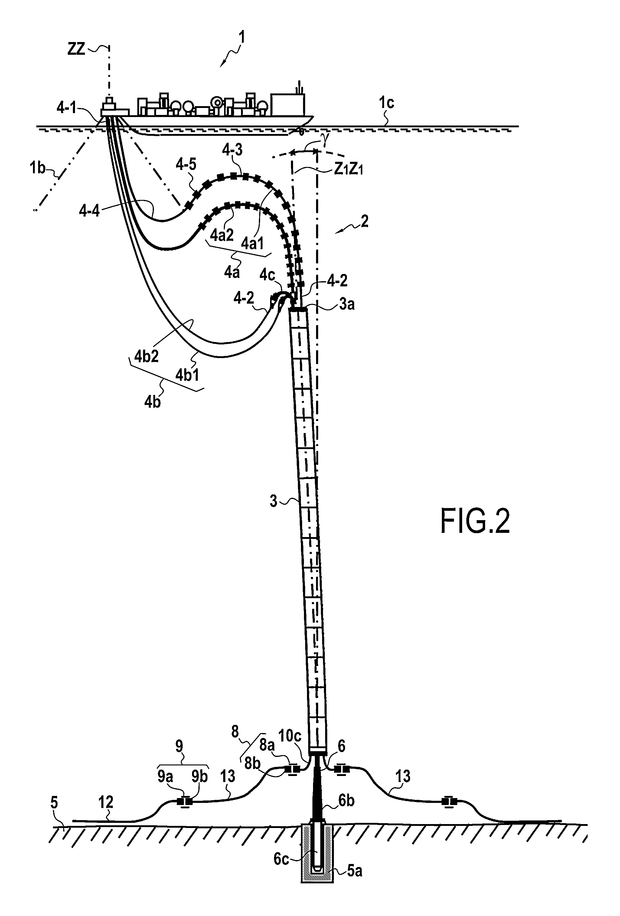
[0166]FIG. 1 is a side view of an FPSO type floating support 1 anchored on a turret 1a by anchor lines 1b, said turret being situated beyond the stem of the FPSO and being connected to a hybrid tower type bottom-to-surface connection 2 having four flexible pipes 4, 4a-4b, and a multi-riser tower 3. Said flexible pipes 4 are connected to the top of the tower 3, each flexible pipe 4 being connected to a respective one of the rigid pipes 10 of said multi-riser tower 3, as explained in greater detail in the description below of the invention.

[0167]Two first flexible pipes 4a, numbered 4a1 and 4a2 present floats 45 over a portion 43 of their length, thereby imparting positive buoyancy thereto and thus ensuring continuously varying curvature facing downwards or towards the bottom 5 up to the point of connection with the top end 10a of a substantially rectilinear rigid pipe 10 of the tower, i.e. a pipe of radius of curvature that is therefore substantially infinite, or in other words its c...


PUM


Abstract

A bottom-to-surface connection installation having a floating support and a turret and having: a plurality of risers having their top ends secured to a carrier structure a plurality of flexible pipes extending from the turret to the top ends of the risers; the flexible pipes including at least two first flexible pipes with positive buoyancy positioned at different heights; and guide modules secured to a tension leg and suitable for sliding along floats of the risers.

Description

PRIORITY CLAIM[0001]This is a U.S. national stage of application No. PCT / FR2013 / 050589, filed on Mar. 19, 2013. Priority is claimed on French Application No.: FR 1252542 filed Mar. 21, 2012, the content of which is incorporated herein by reference.FIELD OF THE INVENTION[0002]The present invention relates to an installation of multiple bottom-to-surface connections between undersea pipes resting on the sea bottom and a floating support on the surface, the installation comprising a hybrid tower made up of a plurality of flexible pipes connected to a plurality of rigid riser pipes, or vertical risers, with the bottom end of the hybrid tower secured to an anchor device comprising a base arranged at the sea bottom.[0003]The technical sector of the invention is more particularly the field of fabricating and installing production risers for off-shore extraction of oil, gas, or other soluble or fusible material or a suspension of mineral material from an undersea well head to a floating sup...

Claims


Application Information

Patent Timeline
Patent Type & Authority Patents(United States)
IPC IPC(8): E21B17/01E21B19/00E21B17/08E21B17/18E21B17/20E21B43/013
CPCE21B19/002E21B17/012E21B17/085E21B17/18E21B17/20E21B43/013
Inventor PIONETTI, FRANCOIS REGIS
Owner SAIPEM SA
Why Eureka
Try Eureka