Eureka AIR delivers breakthrough ideas for toughest innovation challenges, trusted by R&D personnel around the world.

Hybrid carburetor and fuel injection assembly for an internal combustion engine

a hybrid carburetor and internal combustion engine technology, which is applied in the direction of liquid fuel feeders, machines/engines, mechanical equipment, etc., can solve the problems of high cost of hybrid assemblies, and insufficient atomization of fuel

Active Publication Date: 2015-08-25
HOLLEY PERFORMANCE PRODUCTS
View PDF13 Cites 38 Cited by
  • Summary
  • Abstract
  • Description
  • Claims
  • Application Information

AI Technical Summary

Benefits of technology

The present invention is about a hybrid fuel injection and carburetor assembly for delivering a fuel and air mixture into an internal combustion engine. This assembly has a housing with at least one bore that presents a Venturi-shaped region of low pressure, and a valve attached to the housing for controlling the air flow through the bore. The housing also has an aperture that extends between the housing and the low-pressure region of the Venturi-shaped bore, and a fuel injector in fluid communication with the housing for delivering fuel into the cavity. This results in a fuel and air mixture that burns more efficiently than other hybrid assemblies, and can be used with carburetors without significant modification. The high-pressure cavity is created by a shoulder generated in the air flow and the housing has a groove and an insert with a plurality of apertures spaced uniformly around the outer surface of the insert, which helps to distribute the fuel uniformly around the Venturi-shaped bore. Overall, this hybrid assembly improves the performance and efficiency of the fuel injection system and is modular for easy customization.

Problems solved by technology

As one of ordinary skill in the art will appreciate, it is very costly to convert a carbureted engine to fuel injection using conventional processes because certain components of the engine must be modified or replaced in order to accommodate the fuel injectors.
However, such hybrid assemblies are often very costly to manufacture and may not provide sufficient atomization of the fuel into the flow of air.

Method used


Image

  • Hybrid carburetor and fuel injection assembly for an internal combustion engine
  • Hybrid carburetor and fuel injection assembly for an internal combustion engine
  • Hybrid carburetor and fuel injection assembly for an internal combustion engine

Examples


Embodiment Construction

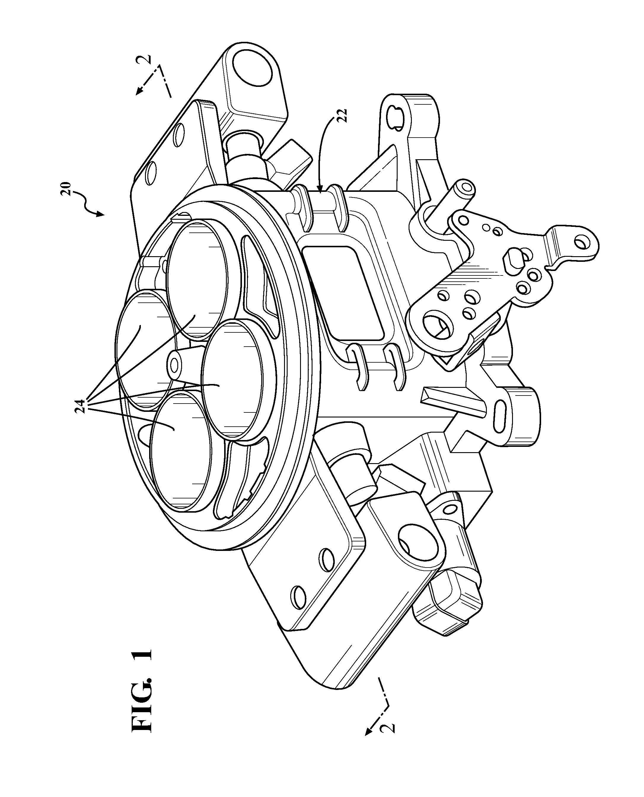
[0014]Referring to the Figures, wherein like numerals indicate corresponding parts throughout the several views, an exemplary hybrid carburetor and fuel injector assembly 20 for delivering a fuel and air mixture into an intake manifold (not shown) of an internal combustion engine (not shown) is generally shown in FIG. 1. The exemplary fuel injection assembly 20 may be used with a wide range of different types of internal combustion engines for any type of vehicle including automobiles and boats and is preferably packaged and sold as an aftermarket product to be mounted on an existing engine. Of course, the exemplary fuel injector assembly 20 could alternately be packaged and sold in conjunction with the engine.

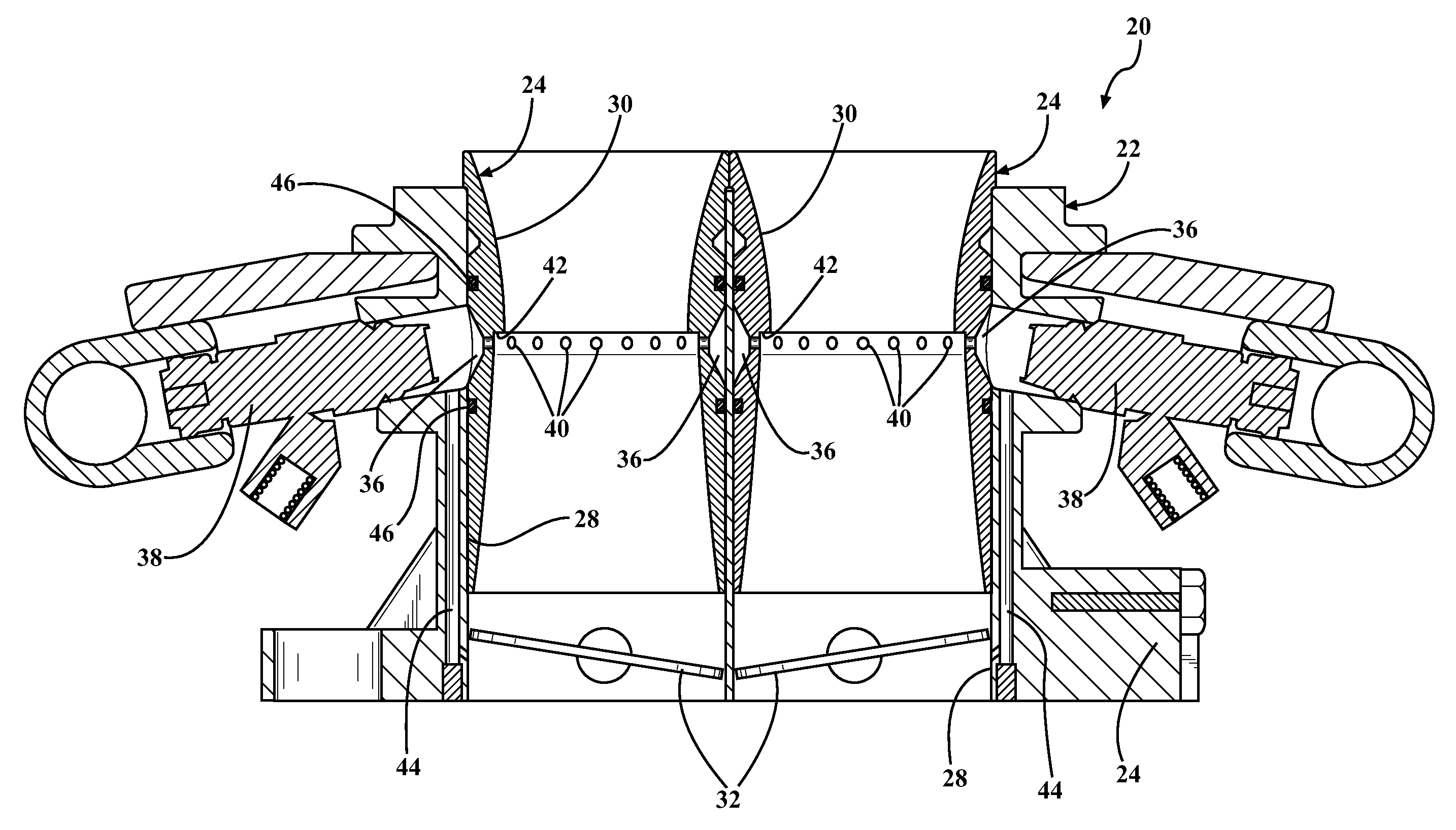
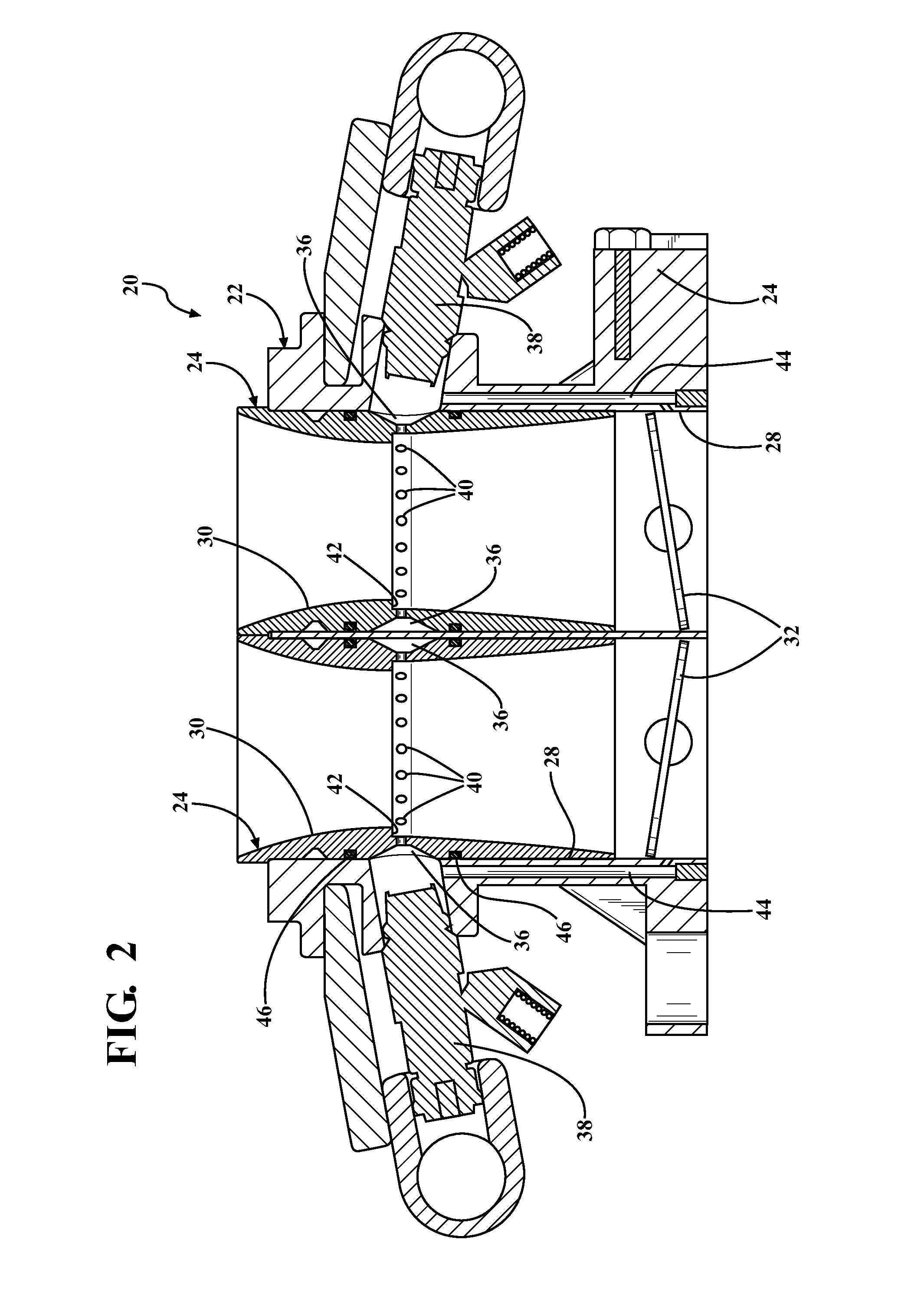
[0015]Referring now to the cross-sectional view of FIG. 2, the exemplary fuel injection assembly 20 includes a housing 22 having a body portion 24 and a plurality of inserts 26. The housing 22 portion includes four generally cylindrically-shaped bores 28 spaced from one anothe...


PUM


Abstract

A hybrid fuel injection and carburetor assembly for delivering a fuel and air mixture into an intake manifold of an engine is provided. The assembly includes a housing and a plurality of inserts with Venturi-shaped bores to establish low pressure regions in the flow of air. The housing and inserts cooperate with one another to present cavities, and the inserts include apertures extending between the cavities and the low-pressure regions. The assembly also includes fuel injectors in fluid communication with the cavities. In operation, fuel is injected at a high pressure into the cavities to the point, and the pressurized fuel is delivered into the low pressure air via the apertures. Because of the large pressure difference between the pressurized fuel in the cavities and the low pressure air, the fuel becomes very atomized.

Description

BACKGROUND OF THE INVENTION[0001]1. Field of the Invention[0002]The present invention relates generally to a fuel injection assembly for delivering a fuel and air mixture into an intake manifold of an internal combustion engine and to a method of delivering a fuel and air mixture into an intake manifold of an internal combustion engine.[0003]2. Related Art[0004]Despite the ubiquitous use of fuel injection, carburetors remain in use in many internal combustion engines. Generally, carburetors include at least one Venturi-shaped barrel, throttle valve and float bowl. In operation, a vacuum is drawn by a piston, which pulls air through the Venturi-shaped barrel and an intake manifold and ultimately to a combustion chamber. A low pressure region in the Venturi-shaped barrel pulls fuel out of the float bowl to atomize the fuel into the flow of air. In contrast, in most fuel injected engines, a fuel injector propels fuel either into the air just upstream of each cylinders' intake valve or ...

Claims


Application Information

Patent Timeline
Patent Type & Authority Patents(United States)
IPC IPC(8): F02D9/08F02M69/04F02M19/08F02M17/34F02M61/14
CPCF02M17/34F02M19/08F02M69/044
Inventor BENOIT, MARVIN V.
Owner HOLLEY PERFORMANCE PRODUCTS
Why Eureka
Eureka Blog
Learn More