
Electrical heating device

a heating device and electric technology, applied in the direction of fluid heaters, air heaters, lighting and heating apparatuses, etc., can solve problems such as easy failure, and achieve the effect of simple construction

Active Publication Date: 2015-08-25
EBERSPACHER CATEM
View PDF14 Cites 7 Cited by
  • Summary
  • Abstract
  • Description
  • Claims
  • Application Information

AI Technical Summary

Benefits of technology

[0005]The object of the present invention is to further develop the generic electrical heating device. The intention of the present invention is to specify in particular a compactly constructed electrical heating device which is relatively simple in construction and can also be operated at high working pressures of the fluid to be heated.
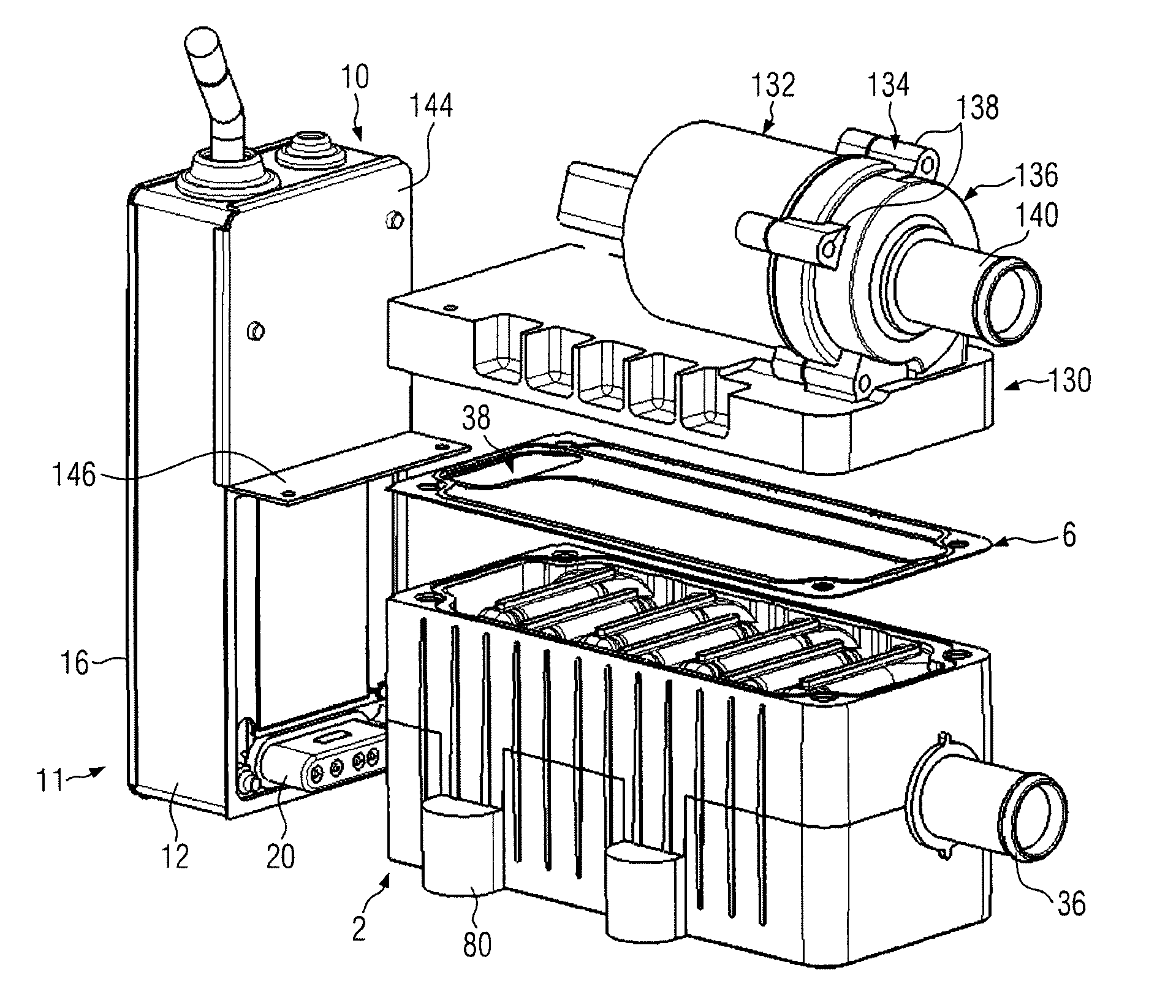
[0007]With the electrical heating device according to the invention the housing which encloses the circulation chamber is closed with a housing cover which is provided in the constructional unit with the pump. In this way a compactly constructed electrical heating device is formed. It is also possible to provide the pump channel situated opposite the circulation chamber and separated by a respectively thin cover or membrane. The hydrostatic pressure on both sides of this membrane basically compensates itself and the construction is overall simplified and nevertheless particularly suitable for operation with high fluid pressures. A thin membrane between the pump channel and the circulation chamber can furthermore be made less thick, further favouring a compact construction.
[0012]However, it is preferable to form tapered ridges on the underside of the heating ribs, the face sides of which are arranged a support level for the covering element. For this purpose the housing cover has corresponding supporting counter ridges. Here, the covering element is clamped for sealing between the supporting ridges and the supporting counter ridges. In the region of the ridges or counter ridges this embodiment offers a relatively high surface pressure, resulting in sealing of the cover plate such that the fluid to be heated can be subjected to a relatively high pressure of more than 35 bar. Here it is preferable if the pump channel is formed with about the width of the heating ribs, i.e. with the whole extent of the supporting ridges in their longitudinal direction opposite the supporting counter ridges, so pressurised fluid is present on both sides of the flat covering element. In this way the pressure difference on the area to be sealed within the housing is minimised.
[0013]The supporting ridges are tapered, i.e. they have a thickness which is less than the thickness of the heating ribs. Thickness in this sense is normally taken to mean an extension which runs at right angles to the insertion direction of the FTC heating elements into the U-shaped recesses and at right angles to the longitudinal extension of the FTC heating elements. The heating ribs normally extend transversely to the longitudinal extension of a longitudinal housing. Due to these supporting ridges the covering element is positioned in a supporting level against the housing. There is good sealing of the individual flow sections of the meander-like flow channel, which preferably extend parallel to one another, and of the pump channel, which normally extends at right angles to the main sections of the flow channel. Accordingly, the medium to be heated flows completely through the flow passage. A short-circuit flow, which passes the bottom end of the U-shaped recess, is prevented. The tapered ridges are thinner than the heating ribs, so that heat transfer to the medium in the region of the bottom of the U-shaped recess can also occur, which further improves the thermal efficiency.
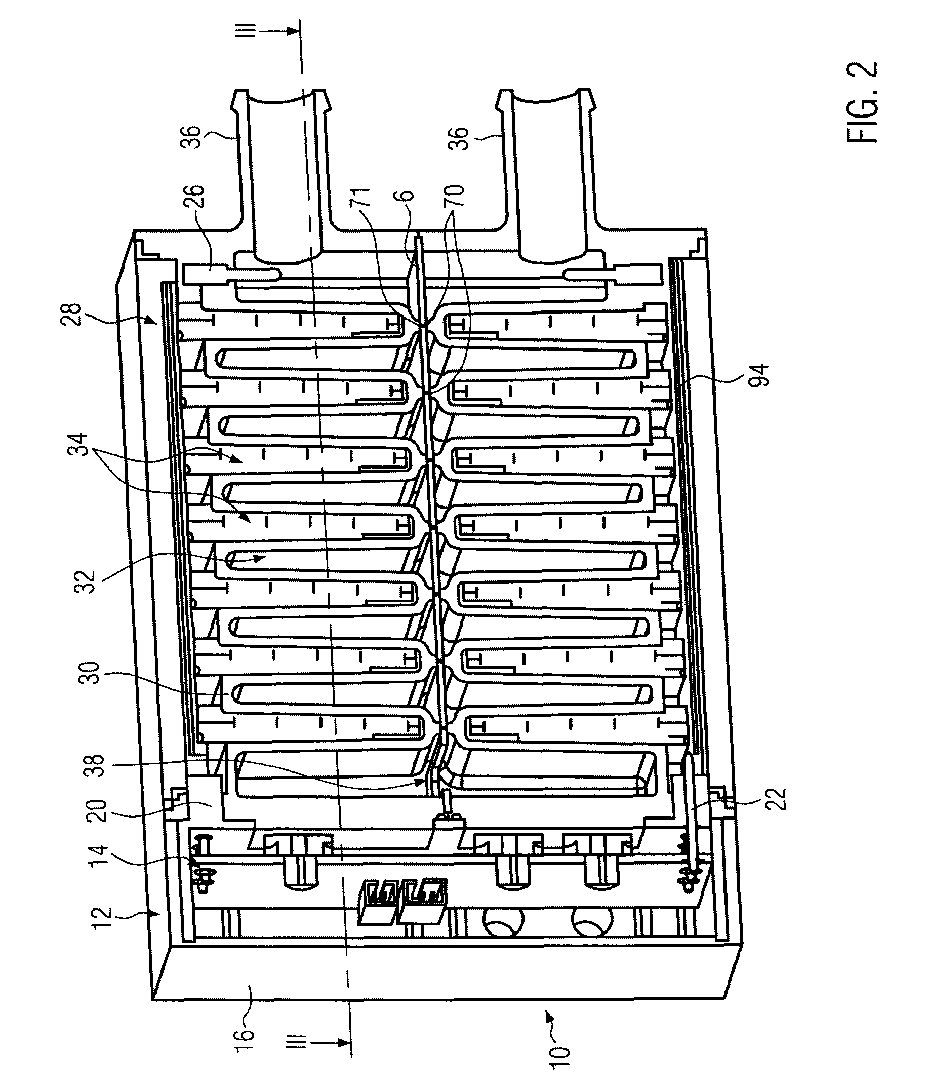
[0016]The meander-type flow guidance in the housing leads to an improved thermal efficiency with respect to the electrical heating device known from EP 1 872 986 A1. With this embodiment the U-shaped recesses extend in the main flow direction within the housing. Due to the permanent deflection of the flow by the meander-type flow guidance, a laminar flow is largely avoided. In particular the heat emitting surfaces of the heating ribs are not subjected to a flow which extends essentially parallel to the surface of the ribs. Instead, due to velocity components of the flow at right angles to the surface of the ribs, good heat transfer and dissipation to the medium to be heated is achieved. Since the PTC heating elements also discharge heat to both oppositely situated face sides, there is good dissipation of the heat produced by the PTC heating elements and thus a higher thermal efficiency.

Problems solved by technology

The medium to be heated can enter the pump directly from the circulation chamber without hose sections, which are susceptible to failure, having to be fitted in an elaborate way between the heating device and the pump.

Method used


Image

  • Electrical heating device
  • Electrical heating device
  • Electrical heating device

Examples


first embodiment

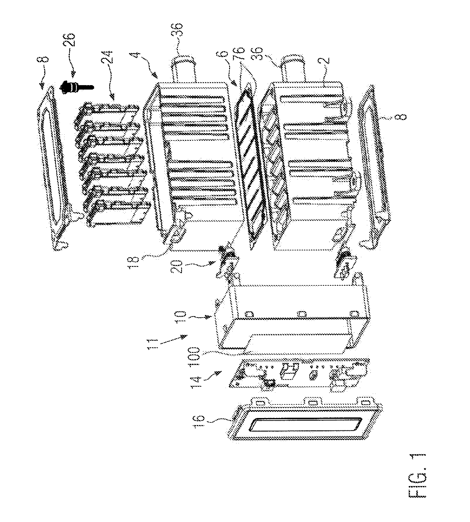
[0041]FIG. 1 illustrates a perspective exploded drawing of an electrical heating device. It comprises a first housing 2 and a second housing 4, formed essentially mirrored to it, which with the intermediate positioning of a covering element 6 are joined together, each being covered on the outside by a housing cover 8.

[0042]On a common face side of the two housings 2, 4 there is a control housing, identified with the reference numeral 10, of a control device 11, which has a control housing frame 12, which accommodates an assembled conductor board 14 and is closed by a control housing cover 16.

[0043]On their face sides facing the control housing 10, both housings 2, 4 have a housing connection opening 18 which is provided close to the housing cover 8. In this control housing connection opening 18 in each case a plug housing 20 can be inserted, which is manufactured from an insulating material, for example plastic, and bears a plurality of plug elements 22, which provide an electrical ...

fourth embodiment

[0067]FIGS. 14 and 15 illustrate a The same components are identified with the same reference numerals compared to the previously discussed embodiment.

[0068]As the previously described embodiments, the fourth embodiment comprises a housing 2 which is joined to a housing cover 148 and mounting flanges 150 for mounting the electrical heating device are fitted to its longitudinal sides. On a face side of the housing 2 and the housing cover 148 there is the control housing 10 with the controller which is accommodated in it and which is not detailed in FIGS. 14 and 15. This control housing 10 is in the present case formed L-shaped with an overhang 152 protruding slightly over the housing cover 148, with two cable clamps 154, 156 mounted on its face sides for mounting and sealing cables secure against twisting and strain. The cable clamp 154 is used for connecting a connecting cable; the larger cable clamp 156 is used for connecting a cable for the power current. The housing 2 is formed ...


PUM


Abstract

An electrical heating device comprises a housing which encloses a circulation chamber through which a medium can flow, and into which heating ribs protrude. Each of the heating ribs has a U-shaped recess which open into a uniform connecting chamber, which is separated from the circulation chamber by a partition wall provided in the region of the open ends of the U-shaped recesses, and which accommodates at least one PTC heating element that abuts oppositely situated inner sides of the U-shaped recess in heat-conducting contact. A housing cover bears a pump and forms a pump channel. The pump channel opens into an inlet opening of the pump, which is formed by a pump housing.

Description

BACKGROUND OF THE INVENTION[0001]1. Field of the Invention[0002]The present invention relates to an electrical heating device with a housing, which encloses a circulation chamber through which a medium can flow, into which heating ribs extend, which each have a U-shaped recess, which open into a uniform connecting chamber, which is separated from the circulation chamber by a partition wall provided in the region of the open ends of the U-shaped recesses, and accommodates at least one PTC heating element, which abuts oppositely situated inner sides of the U-shaped recess in heat-conducting contact.[0003]2. Description of the Related Art[0004]An electrical heating device of this nature is known from EP 1 872 986 A1 which originates from the applicant.SUMMARY OF THE INVENTION[0005]The object of the present invention is to further develop the generic electrical heating device. The intention of the present invention is to specify in particular a compactly constructed electrical heating d...

Claims


Application Information

Patent Timeline
Patent Type & Authority Patents(United States)
IPC IPC(8): B60L1/02F24H1/10F24H1/08H05B3/24
CPCH05B3/24H05B2203/02H05B2203/023B60H1/22F24H3/02H05B3/14
Inventor CLAUSS, MAURICEBOHLENDER, FRANZNIEDERER, MICHAEL
Owner EBERSPACHER CATEM
Learn More