Rotary actuatable closure arrangement for surgical end effector

a technology of end effector and rotary actuator, which is applied in the field of minimally invasive robotic (or “ telesurgical”) systems, can solve the problems of inability to generate the magnitude of force required to effectively cut and fasten tissue, and the limited number of existing robotic surgical systems

Active Publication Date: 2015-09-01
CILAG GMBH INT
View PDF3630 Cites 1455 Cited by
  • Summary
  • Abstract
  • Description
  • Claims
  • Application Information

AI Technical Summary

Problems solved by technology

Many of such systems, however, have in the past been unable to generate the magnitude of forces required to effectively cut and fasten ...

Method used


Image

  • Rotary actuatable closure arrangement for surgical end effector
  • Rotary actuatable closure arrangement for surgical end effector
  • Rotary actuatable closure arrangement for surgical end effector

Examples


Embodiment Construction

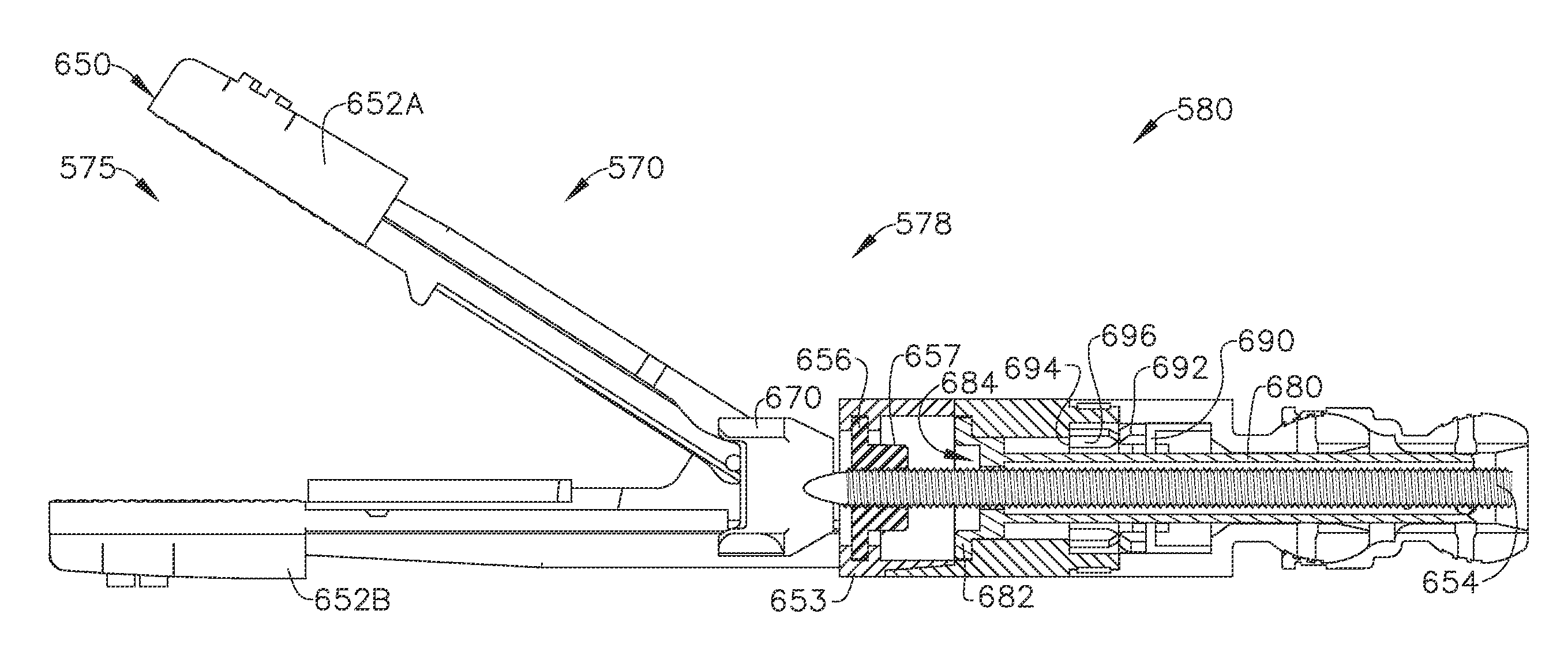
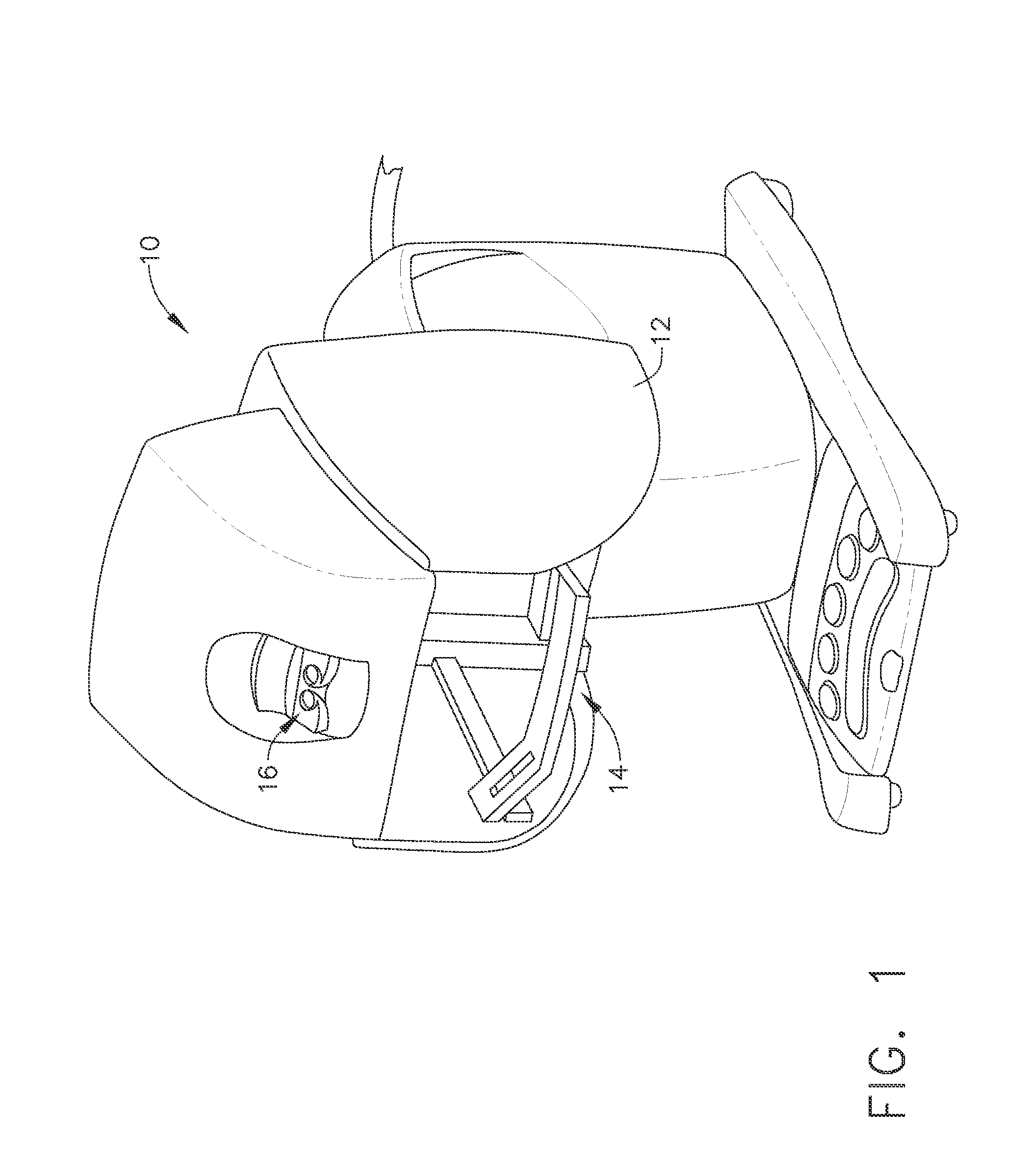
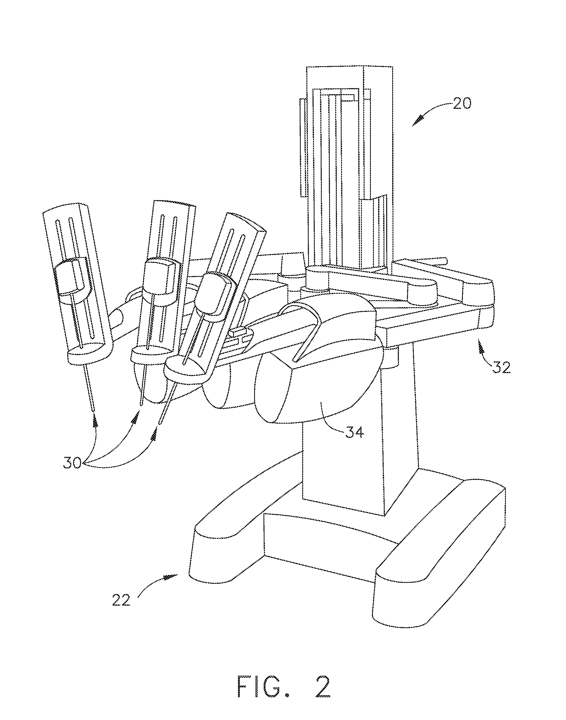
[0167]Applicant of the present application also owns the following patent applications that have been filed on even date herewith and which are each herein incorporated by reference in their respective entireties:[0168]1. U.S. patent application Ser. No. 13 / 536,271, entitled “Flexible Drive Member,” now U.S. Patent Application Publication No. 2014 / 0005708.[0169]2. U.S. patent application Ser. No. 13 / 536,288, entitled “Multi-Functional Powered Surgical Device with External Dissection Features,” now U.S. Patent Application Publication No. 2014 / 0005718.[0170]3. U.S. patent application Ser. No. 13 / 536,277, entitled “Coupling Arrangements for Attaching Surgical End Effectors to Drive Systems Therefor,” now U.S. Patent Application Publication No. 2014 / 0001234.[0171]4. U.S. patent application Ser. No. 13 / 536,326, entitled “Surgical End Effectors Having Angled Tissue-Contacting Surfaces,” now U.S. Patent Application Publication No. 2014 / 0005653.[0172]5. U.S. patent application Ser. No. 13 / 5...


PUM


Abstract

A surgical instrument may include an end effector, an input drive shaft, a closure drive, and/or a firing drive. The end effector may comprise a jaw assembly including a first jaw member and a second jaw member. The end effector may comprise an I-beam member axially translated between a proximal position and a distal position within the end effector. In one embodiment, the input drive shaft may selectively engage the firing drive and/or the closure drive. In one configuration, the closure drive is threadedly engaged with the firing drive allowing the input drive shaft, during a firing stroke, to simultaneously move the closure drive and the firing drive until the closure drive is disengaged from the firing drive. On a reverse stroke, the closure drive may be reengaged with the firing drive.

Description

BACKGROUND[0001]Over the years a variety of minimally invasive robotic (or “telesurgical”) systems have been developed to increase surgical dexterity as well as to permit a surgeon to operate on a patient in an intuitive manner. Many of such systems are disclosed in the following U.S. patents which are each herein incorporated by reference in their respective entirety: U.S. Pat. No. 5,792,135, entitled “Articulated Surgical Instrument For Performing Minimally Invasive Surgery With Enhanced Dexterity and Sensitivity”, U.S. Pat. No. 6,231,565, entitled “Robotic Arm DLUS For Performing Surgical Tasks”, U.S. Pat. No. 6,783,524, entitled “Robotic Surgical Tool With Ultrasound Cauterizing and Cutting Instrument”, U.S. Pat. No. 6,364,888, entitled “Alignment of Master and Slave In a Minimally Invasive Surgical Apparatus”, U.S. Pat. No. 7,524,320, entitled “Mechanical Actuator Interface System For Robotic Surgical Tools”, U.S. Pat. No. 7,691,098, entitled Platform Link Wrist Mechanism”, U.S...

Claims


Application Information

Patent Timeline
IPC IPC(8): A61B17/32A61B17/29A61B19/00A61B18/14A61B17/00
CPCA61B17/29A61B18/1445A61B19/2203A61B2017/00477A61B2017/2903A61B2017/2929A61B2017/2933A61B2017/2939A61B2017/2943A61B2017/320032A61B2018/1455A61B2019/2238A61B17/062A61B2017/00353A61B34/30A61B2034/306
Inventor SHELTON, IV, FREDERICK E.BAXTER, III, CHESTER O.YATES, DAVID C.
Owner CILAG GMBH INT
Why Eureka
Try Eureka