
Measurement and placement techniques in hip resurfacing and the like

a hip resurfacing and measurement and placement technology, applied in the field of measurement and placement techniques used in joint replacement surgery, can solve the problems of joint loosening and consequential failure, pain, extensive and expensive revisions, extreme force loading, etc., and achieve outstanding component positioning and accelerate the learning curve

Inactive Publication Date: 2015-09-01
KUSUMA SHARAT
View PDF37 Cites 14 Cited by
  • Summary
  • Abstract
  • Description
  • Claims
  • Application Information

AI Technical Summary

Benefits of technology

The present invention is a method for accurately positioning components during hip resurfacing surgery. It involves using two-dimensional views to determine the angles and distances from osteo-anatomical artifacts, which are then translated into actual markings and device settings. This allows the surgeon to approach the procedure with the necessary measurements and accurately prepare the femoral head structure, position and affix the femoral cap and acetabular cup components accordingly. The invention accelerates the learning curve for the procedure and achieves better component positioning than previous methods.

Problems solved by technology

Most of the procedures or methods involved material problems that led to joint loosening and consequential failure.
This technique requires massive bone removal and results in extreme loading of force in a leveraging action from the top of the femoral ball to a lower part of the stem.
Over a few years, force applied by vigorous and mostly younger patients can cause the stem to loosen, resulting in failure, pain and need for extensive and expensive revisions.
Additionally, such hips that use large femoral stems with metal on plastic articulations have had problems with dislocation due to small head sizes, as well as wear of the polyethylene acetabular components that have resulted in relatively rapid failures.
One of the significant challenges of more general adoption of hip resurfacing is the accurate positioning of the femoral cap and its alignment with respect to the resurfaced femoral head, as well as the complementary alignment and positioning of the concave, hemispherical acetabular insert piece with which the femoral cap cooperates.
One of the major issues with adoption of this procedure in the United States over the past 6 or 7 years has been extremely difficult achieving appropriate component positioning.
Accurate and reproducible component positioning is very challenging because the constituent joint bones are very irregularly shaped, and do not lend themselves to easy measurement in all of the dimensions necessary to resurface and reintroduce the bones into a cooperative, jointed disposition.
Various methods have been tried for this including computer navigation with very expensive computer navigation technology from companies such as Brain Lab.
Such long learning curves extend the period during which there is a risk of less than optimal placement and installation, often requiring additional surgery to ultimately obtain a satisfactory result.

Method used


Image

  • Measurement and placement techniques in hip resurfacing and the like
  • Measurement and placement techniques in hip resurfacing and the like
  • Measurement and placement techniques in hip resurfacing and the like

Examples


Embodiment Construction

[0047]In accordance with the foregoing summary, the following provides a detailed description of the preferred embodiment, which is presently considered to be the best mode thereof.

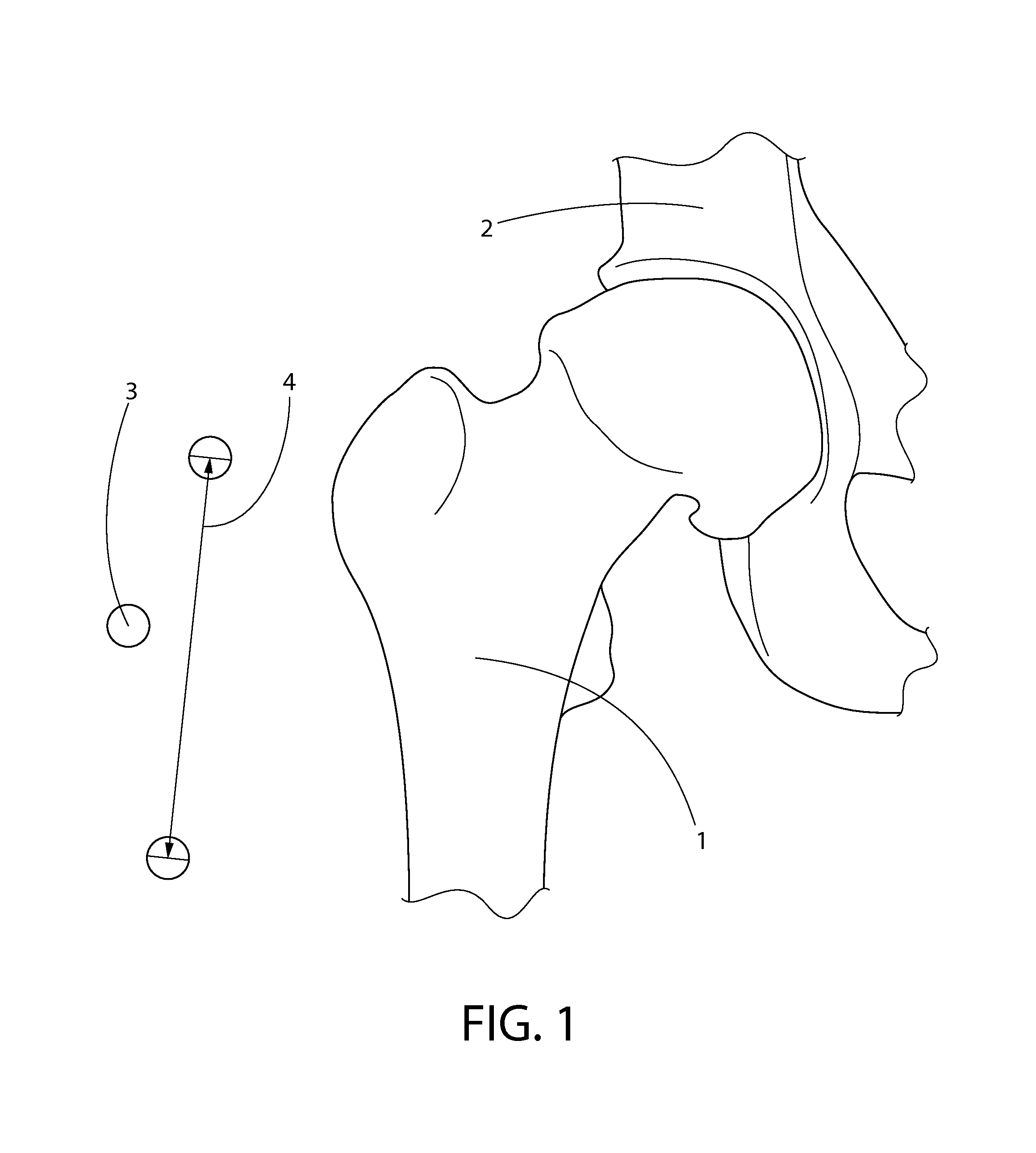
[0048]FIG. 1 is an x-ray image showing image scaling, a first step in the measurement and component placement process, in accordance with the described embodiment of the present invention. This shows the scaling process whereby the marker ball device is used to confirm the scaling / sizing of the x-ray. The first step of the technique is best performed on very detailed and high quality anterior or posterior pelvis radiographs as well as anterior and posterior radiographs of the affected hip along with a lateral x-ray of the affected hip. This may typically be obtained from an image stored in the electronic medical records of the patient, such as a Picture Archiving and Communication System (PACS) radiology system (such as, for example, the Synapse system commercially available from Fuji USA or the NovoPACS ...


PUM


Abstract

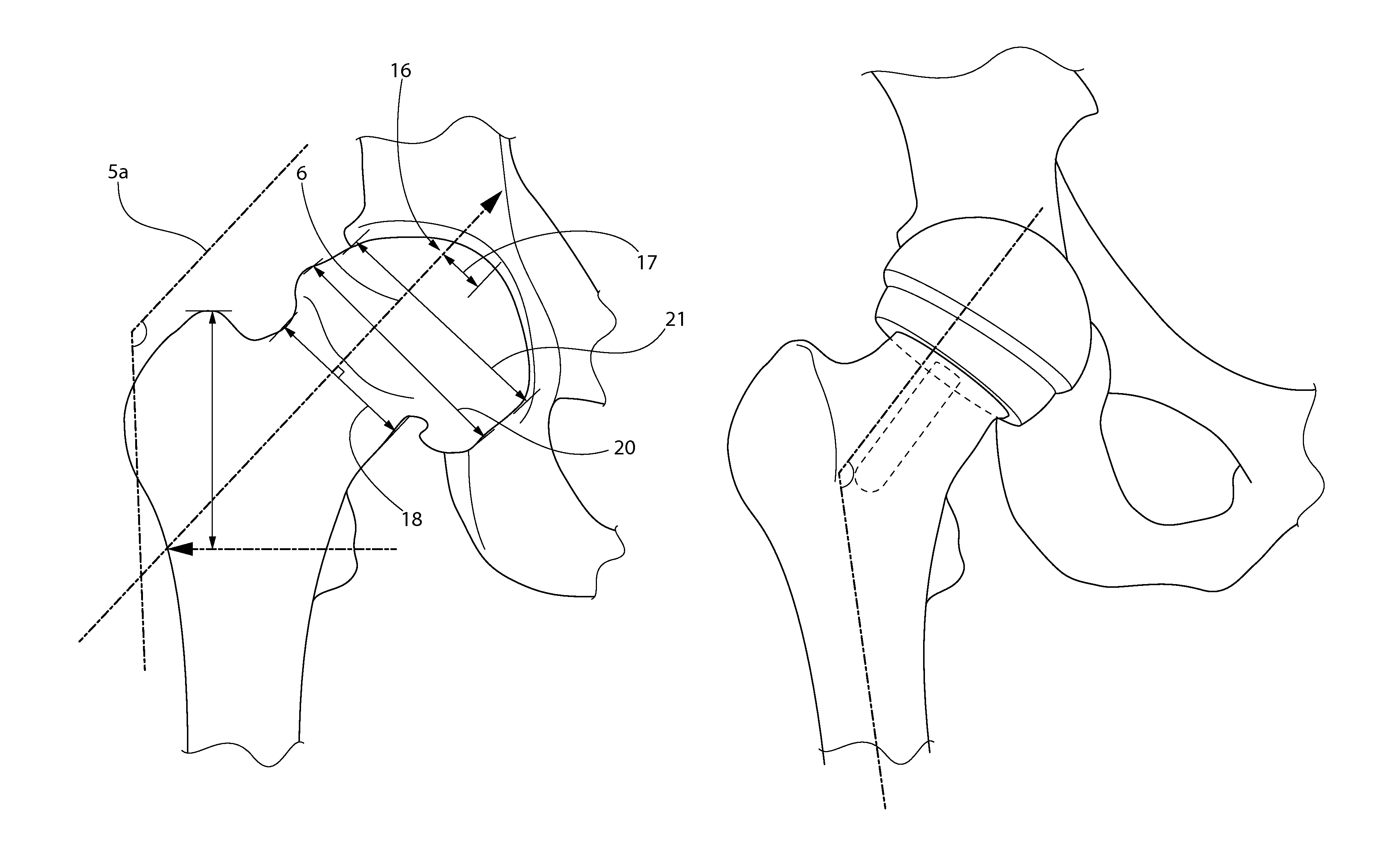
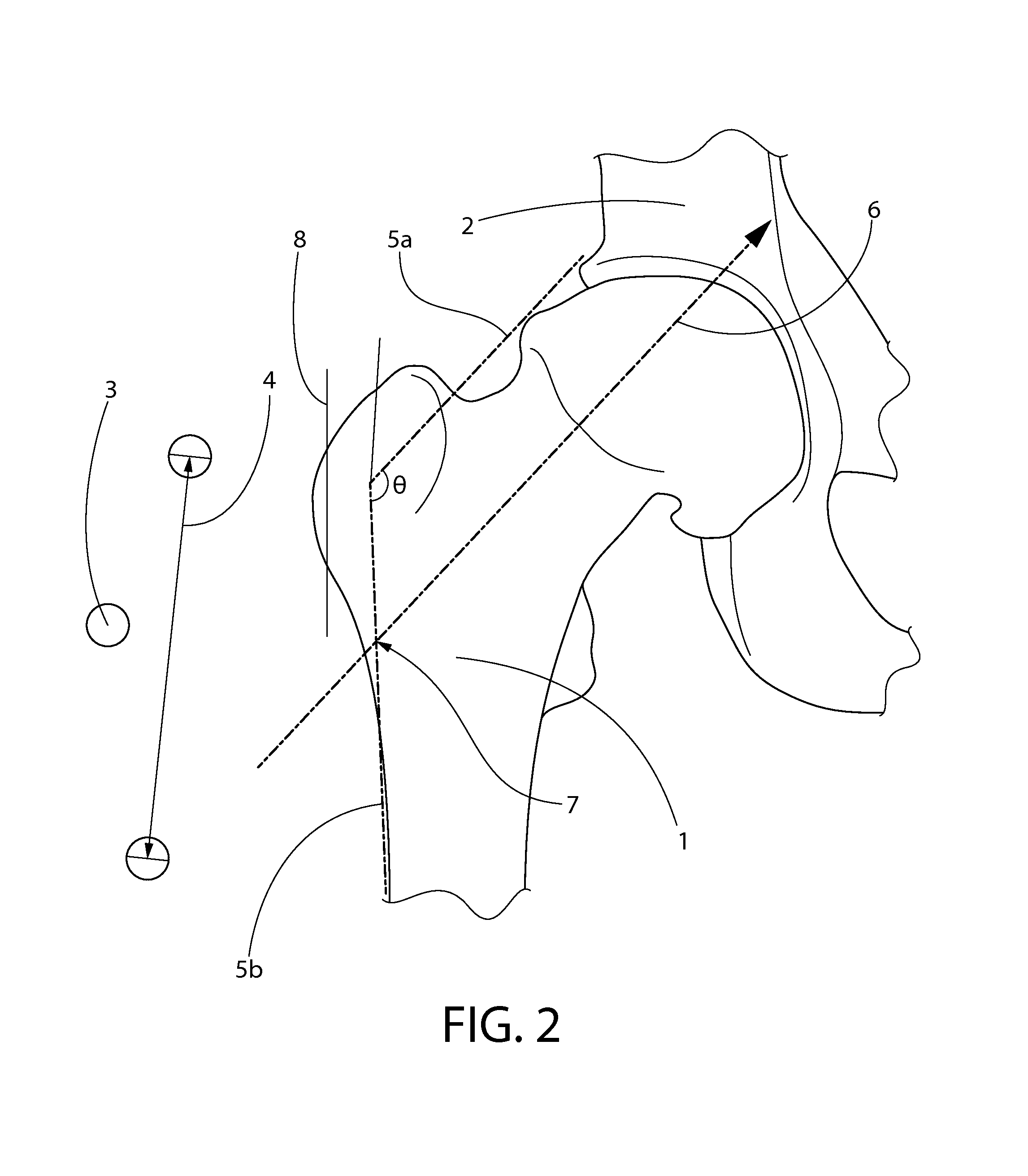
The present invention includes a measurement / assessment technique based upon a collection of angular and distance measurements taken with respect to x-ray visible osteo-anatomical artifacts to arrive at accurate and easily reproducible component placement. In the context of hip arthroplasty surgery the method of the present invention involves determinations, from two different two-dimensional views, of the angles and distances from osteo-anatomical artifacts, to allow a surgeon to approach a hip resurfacing operation with the distance and angular measurements to be translated into actual markings and device settings to be able to accurately ream the femoral head structure, position and affix the femoral cap and acetabular cup components in accordance with the pre-determined distance and angular measurements.

Description

RELATED APPLICATION DATA[0001]This application claims the priority benefit of U.S. Provisional Application Ser. No. 61 / 525,104, filed Aug. 18, 2011, and U.S. Provisional Application Ser. No. 61 / 596,421, filed Feb. 8, 2012, which are hereby incorporated in their entirety herein by reference.FIELD OF THE INVENTION[0002]The present invention relates to measurement and placement techniques used in joint replacement surgery, such as resurfacing hip-joint implants and the like, as well as to surgical operations carried out using the described techniques.BACKGROUND OF THE INVENTION[0003]A natural hip joint may undergo degenerative changes due to a variety of etiologies. When these degenerative changes become so far advanced and irreversible, it may ultimately become necessary to replace a natural hip joint with a prosthetic hip.[0004]Various partial or complete replacements of the hip joint have been proposed and used since the early 1900's. Most of the procedures or methods involved mater...

Claims


Application Information

Patent Timeline
IPC IPC(8): A61B17/56A61F2/36A61B17/16A61B17/88A61B17/74A61F2/32A61F2/34
CPCA61F2/36A61B17/1664A61B17/56A61F2/34A61B17/1666A61F2/32A61B17/74A61B17/748A61B17/1668A61B17/742A61B17/175A61B2017/564A61F2/4657A61F2/3603A61F2002/4668A61B2090/067
Inventor KUSUMA, SHARAT
Owner KUSUMA SHARAT
Learn More