Electromechanical temperature regulation system for providing tempered mix water

a temperature regulation system and electromechanical technology, applied in the direction of temperature control using digital means, process and machine control, instruments, etc., can solve the problems of increasing the temperature of the outlet water, the expansion of the temperature sensitive valve element, and the high cost of the valve of this type, so as to achieve simple, economical and reliable

Active Publication Date: 2015-09-01
PVI IND +1
View PDF10 Cites 9 Cited by
  • Summary
  • Abstract
  • Description
  • Claims
  • Application Information

AI Technical Summary

Benefits of technology

[0012]It is therefore the object of the present invention to provide a simple, economical and reliable temperature regulation system for supplying tempered water having a desired set point temperature without significant temperature fluctuation, also having the required system response time.

Problems solved by technology

A sudden drain on the cold water supply may drop the cold water pressure, while leaving the hot water pressure relatively constant, thus increasing outlet water temperature due to an imbalance between hot and cold inlet water flow.
If the resulting mixed water temperature is too hot, the temperature sensitive valve element will typically expand or move in response to the temperature increase.
One disadvantage of this typical class of mechanical TMV is that valves of this type tend to be quite expensive, for example, on the order of $8000-$10,000 per valve.
Another disadvantage of the prior art temperature balancing valves and many electronically controlled mixing valves described in the prior art is the inability to stabilize outlet water temperature at extremes of flow rate.
This is due to several technical issues such as the velocity of water in the plumbing lines, the thermal lag of the water temperature sensor and mechanical overshoot in the thermal governor cartridge assembly or motor / belt drive of electronically controlled thermostatic valves.

Method used


Image

  • Electromechanical temperature regulation system for providing tempered mix water
  • Electromechanical temperature regulation system for providing tempered mix water
  • Electromechanical temperature regulation system for providing tempered mix water

Examples


Embodiment Construction

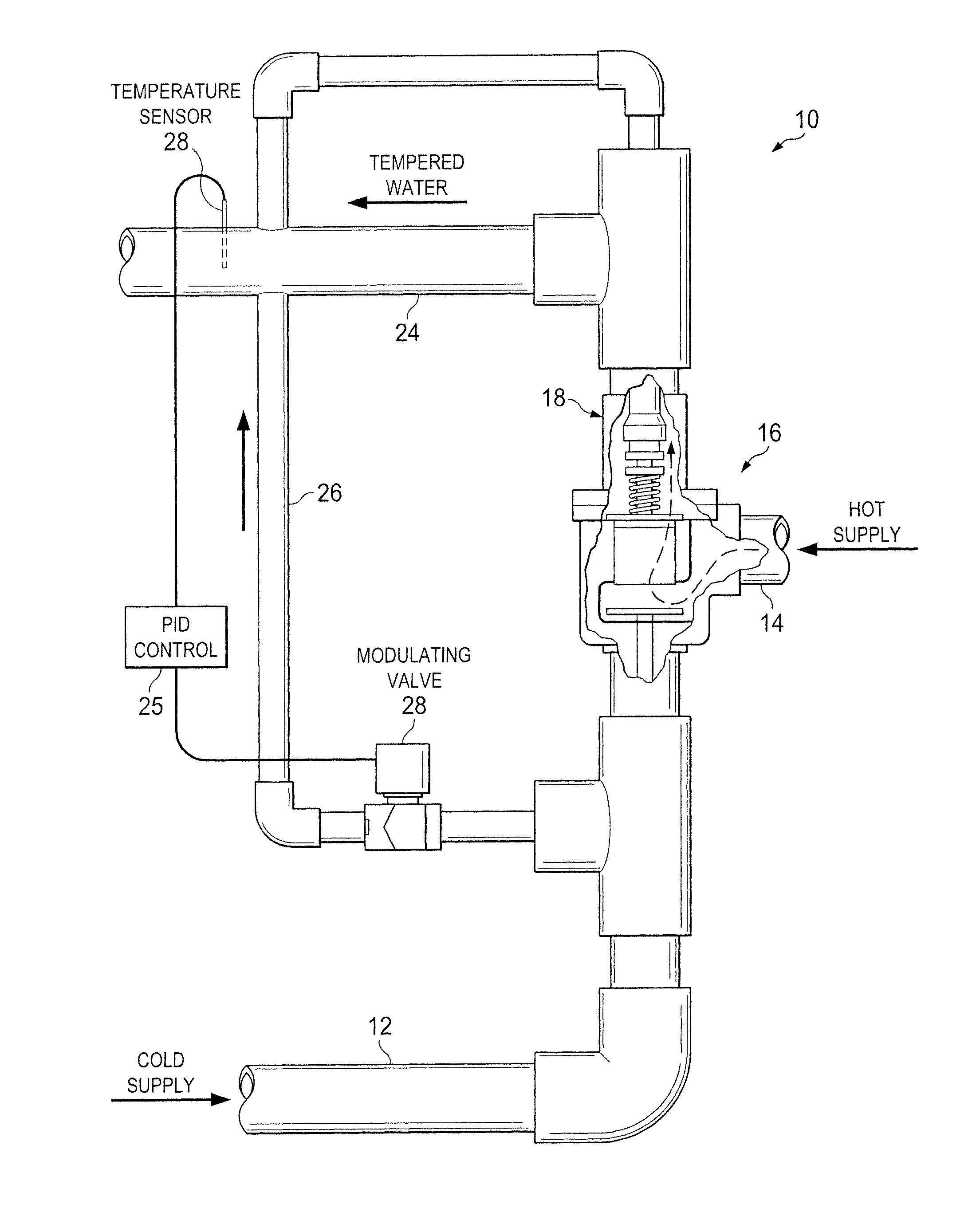
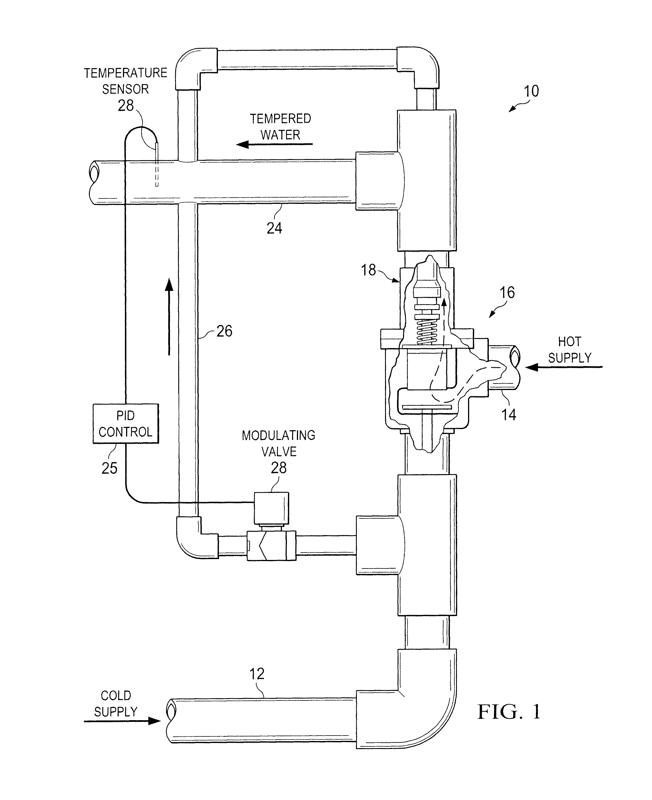
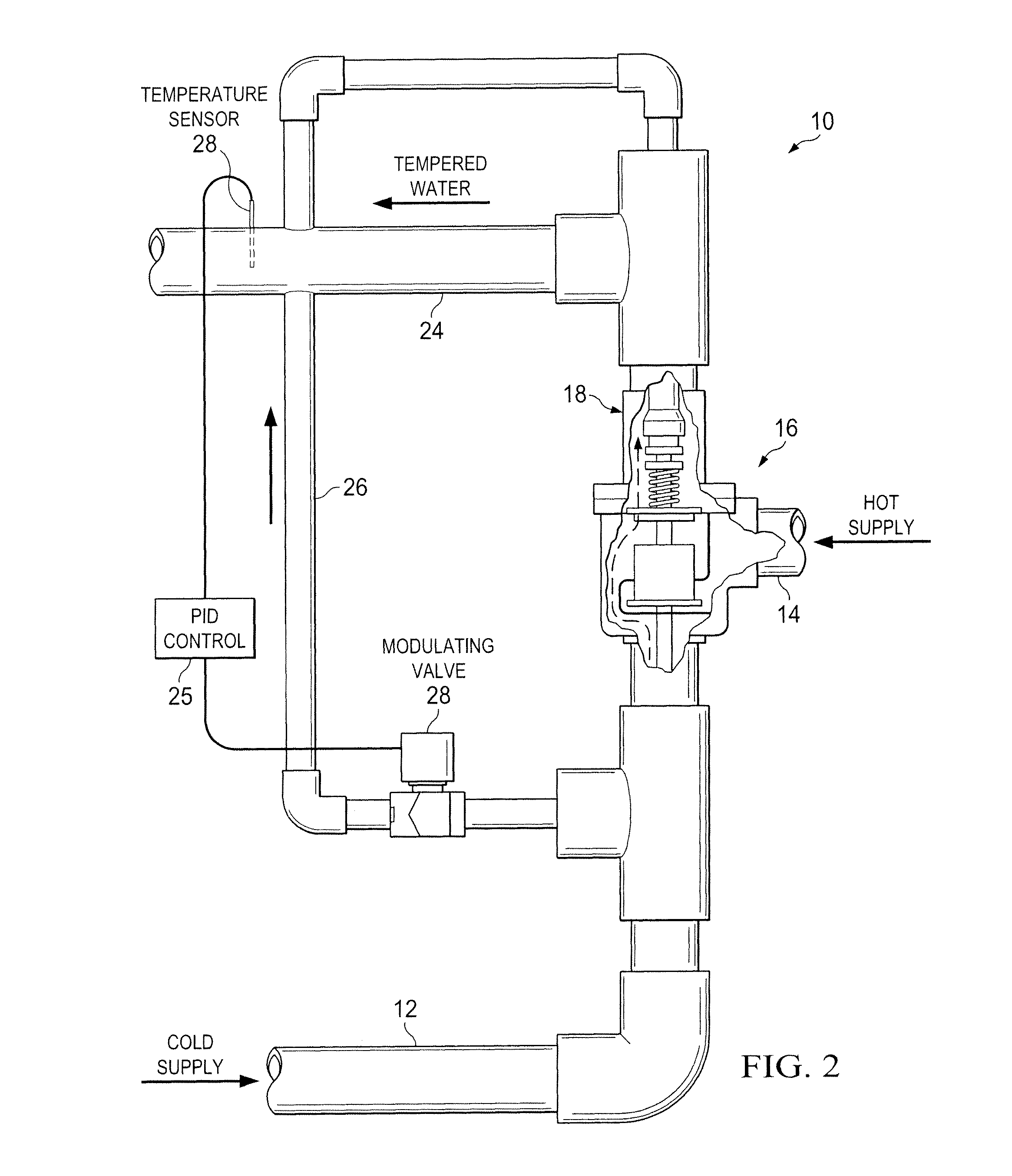
[0021]FIGS. 1-3 are simplified, partly schematic views of the temperature regulation system of the invention, showing the operative components there in the hot-only, cold-only, and hot and cold operating positions, respectively. FIGS. 4-6 are close-up views of the thermostatic mixing valve which is used in the system of the invention in the same three operating positions. Thus, with respect to FIG. 1 of the drawings, there is shown the preferred embodiment of the tempered water system 10 of the present invention, having a cold water inlet conduit or supply line 12, a hot water inlet conduit 14 and a three-way mechanically operated thermostatic mixing valve 16.

[0022]As can be seen in FIG. 4, the thermostatic mixing valve 16 of the invention comprises a valve body 18 (FIG. 4) having cold-water inlet 18a, hot-water inlet 18b, and a tempered water outlet 18c. The cold-water inlet 18a and hot-water inlet 18b are connectable to the pressurized cold and hot water inlet conduits 12, 14, con...


PUM


Abstract

A thermostatic mixing valve is used in a tempered water blending system. A cold water bypass line in the system acts under the control of a modulating valve and electronic controller to divert cold water back to a temperature sensing element in the mixing valve. By flooding the temperature sensing element, the mixing valve detects a false temperature and adjusts its flow rate of hot and cold water accordingly. The electronic controller acts in reverse of normal fashion, providing negative feedback to the sensing element of the mixing valve.

Description

BACKGROUND OF THE INVENTION[0001]1. Field of the Invention[0002]The present invention relates to tempered water mixing systems where cold and hot water supplies are thermostatically blended to provide a tempered discharge outflow of water at a selected temperature.[0003]2. Description of the Prior Art[0004]Thermostatic mixing valves (TMVs) have been in use for many years to control the temperature of water supplied to a delivery point. Thermostatic control valves of this general type are well known, e.g., as shown in U.S. Pat. Nos. 4,739,793; 4,767,052; and 5,647,531. These valves are well known to those skilled in the art. TMVs are capable of delivering water at a preset temperature, as well as preventing water flow in the event of the failure of the cold water supply. They are used extensively in hospitals, nursing homes and similar facilities. A particular application would be, for example, for supplying water to plumbing fixtures such as showers, large medical bathing systems or...

Claims


Application Information

Patent Timeline
Patent Type & Authority Patents(United States)
IPC IPC(8): G05D23/19G05D23/13
CPCG05D23/1917G05D23/1306G05D23/1393
Inventor FERGUSON, MARK A.
Owner PVI IND
Why Eureka
Try Eureka