Joint mechanism and supporting device therewith

a joint mechanism and supporting device technology, applied in the direction of folding chairs, furniture parts, and wheelchairs with multiple axes, can solve the problems of inability to stand, limitation of use of supporting devices, and inconvenient folding of supporting devices, so as to effectively fold or unfold supporting components easily and conveniently

Active Publication Date: 2015-09-08
WONDERLAND SWITZERLAND AG
View PDF9 Cites 11 Cited by
  • Summary
  • Abstract
  • Description
  • Claims
  • Application Information

AI Technical Summary

Benefits of technology

[0006]A purpose of the present invention is to provide a joint mechanism and a supporting device therewith capable of being folded and operated easily and conveniently, to solve the problems mentioned above.
[0030]The joint mechanism and the supporting device therewith can effectively fold or unfold the supporting components easily and conveniently.

Problems solved by technology

Besides, it is inconvenient to fold the supporting device, and the folded supporting device is not able to stand so as to be carried inconveniently.
The conventional mechanical design of the supporting device brings limitation in using the supporting device.
Therefore, it is a significant issue to solve these problems.

Method used


Image

  • Joint mechanism and supporting device therewith
  • Joint mechanism and supporting device therewith
  • Joint mechanism and supporting device therewith

Examples


Embodiment Construction

[0039]In the following detailed description of the preferred embodiments, reference is made to the accompanying drawings which form a part hereof, and in which is shown by way of illustration specific embodiments in which the invention may be practiced. In this regard, directional terminology, such as “top,”“bottom,”“front,”“back,” etc., is used with reference to the orientation of the Figure(s) being described. The components of the present invention can be positioned in a number of different orientations. As such, the directional terminology is used for purposes of illustration and is in no way limiting. Accordingly, the drawings and descriptions will be regarded as illustrative in nature and not as restrictive.

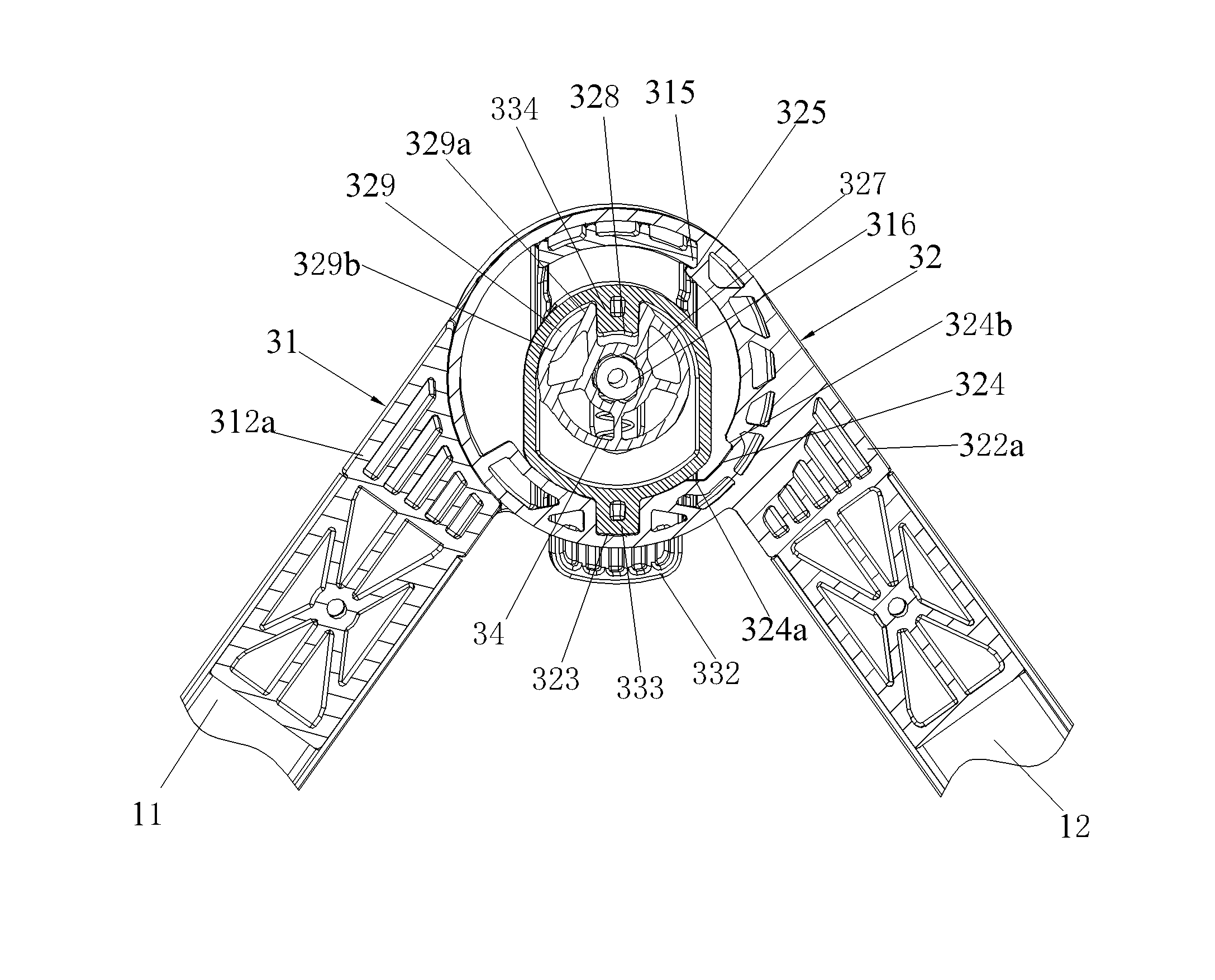
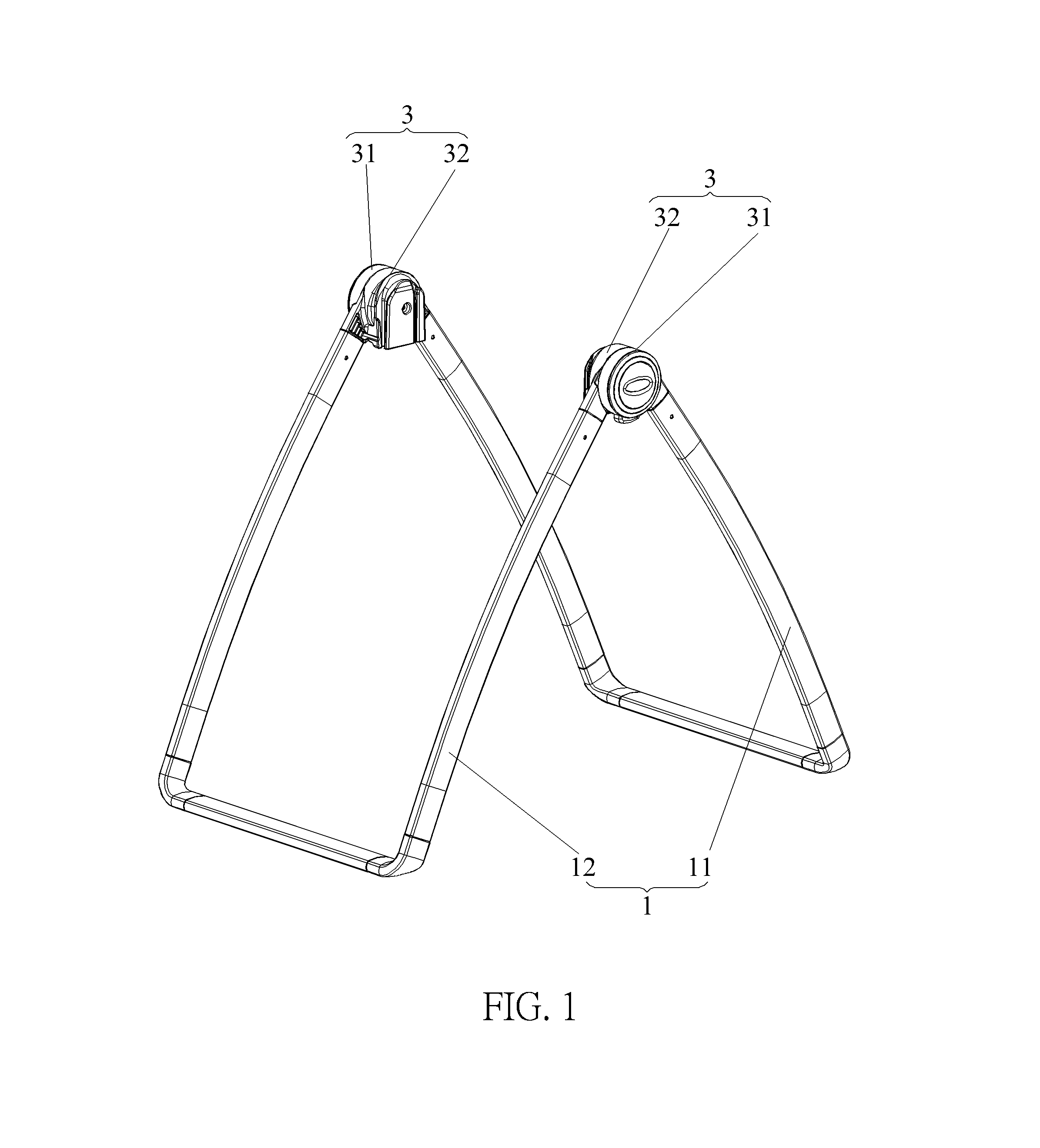
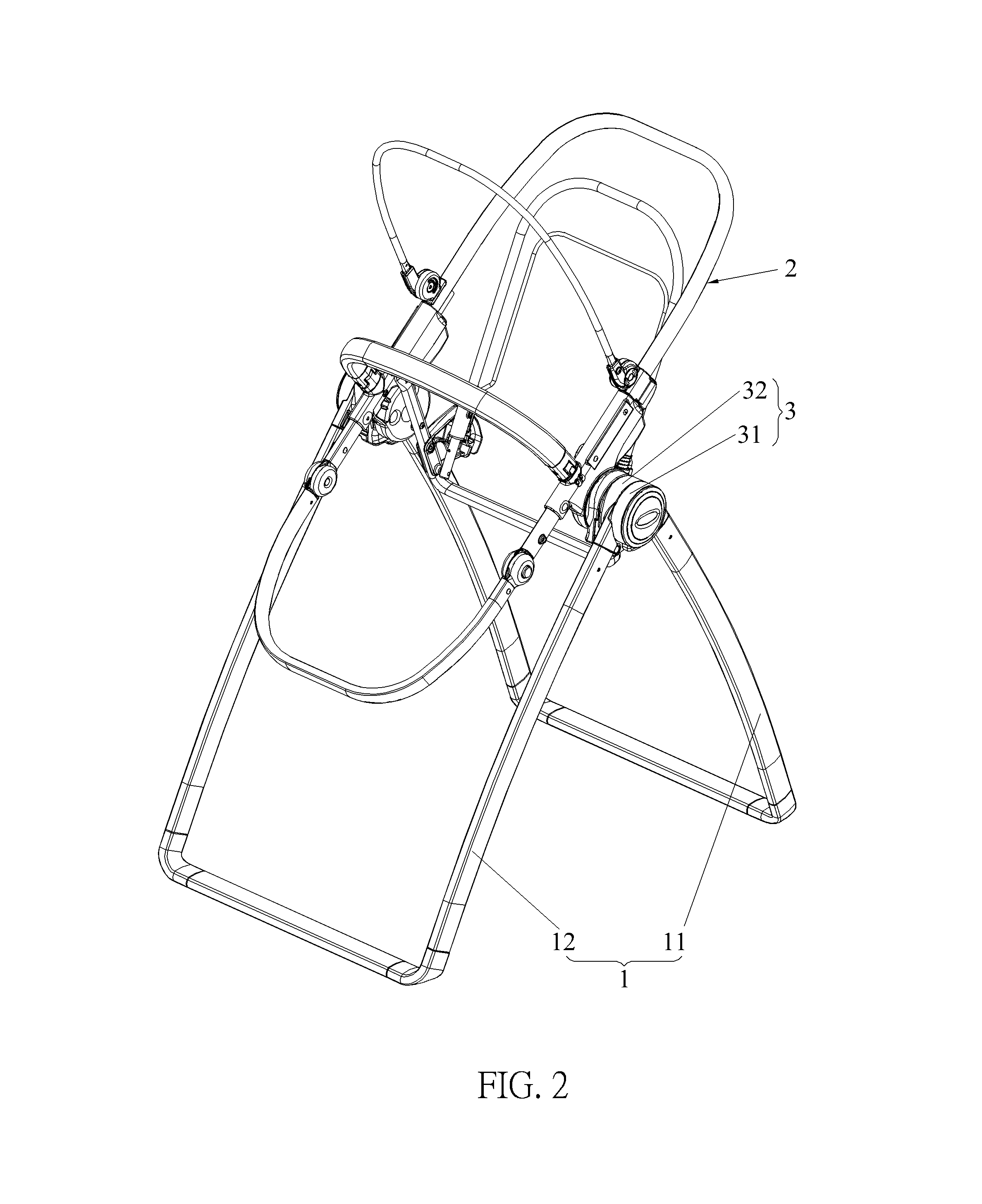
[0040]Please refer to FIG. 1 to FIG. 4. FIG. 1 is a diagram of a supporting device 1 according to an embodiment of the present invention. FIG. 2 to FIG. 4 are assembly diagrams of the supporting device 1 in different applications according to the embodiment of the present i...


PUM


Abstract

The present invention relates to a joint mechanism connected to at least two supporting components of a supporting device. The joint mechanism includes a first joint component connected to one of the at least two supporting components, a second joint component connected to the other of the at least two supporting components and pivoted to the first joint component, and a triggering component movably connected to the first joint component for selectively engaging with or separating from the second joint component. The joint mechanism facilitates folding or unfolding the supporting device. The present invention further relates to the supporting device with the joint mechanism.

Description

BACKGROUND OF THE INVENTION[0001]1. Field of the Invention[0002]The present invention relates to a joint component and a supporting device therewith, and more especially, to a joint component and a supporting device therewith with convenient and easy operation.[0003]2. Description of the Prior Art[0004]There are different kinds of infant carriers in the market, such as a traditional weaving basket and a carrier adapting to a child safety seat in vehicle. An infant carrier shows its excellence and applicability as moving a child by hand or by vehicles. It can solve a problem of being unable to put down a baby even though a career feels tired as carrying baby in arms or that the baby is too little to be fastened by a seatbelt or other fasten belt. It is convenient for parents in taking the child outdoors as using the infant carrier.[0005]However, the infant carrier needs to be put on a particular infant carriage or a particular supporting device. There are many kinds of the infant car...

Claims


Application Information

Patent Timeline
Patent Type & Authority Patents(United States)
IPC IPC(8): A47B91/00F16M11/00A47D1/02A47D9/00F16C11/10
CPCF16C11/10A47D1/02A47D9/005F16M11/00F16C2314/70Y10T403/32262A47D1/023A47D9/016A47D1/10A47D13/027A47D13/02B62B7/06F16C11/045
Inventor SHAN, LIN-HAI
Owner WONDERLAND SWITZERLAND AG
Why Eureka
Try Eureka