Check patentability & draft patents in minutes with Patsnap Eureka AI!

Up-concentration of organic microobjects for microscopic imaging

a microorganism and up-concentration technology, applied in the field of apparatus or system for analyzing a sample fluid containing organic microorganisms, can solve the problems of limiting medical practitioners to a guessing game using a broad antibiotic spectrum, not only economically expensive, but also the need for complex mechanics with high accuracy, and achieve the effect of reducing the total assay tim

Active Publication Date: 2015-09-08
KONINK PHILIPS ELECTRONICS NV
View PDF26 Cites 1 Cited by
  • Summary
  • Abstract
  • Description
  • Claims
  • Application Information

AI Technical Summary

Benefits of technology

[0018]generating an image of the microobjects accumulated on the filter;wherein the throughput V1 / T1 of the step of up-concentrating is greater than the throughput V3 / T3 of the step of filtering. Thus the step of up-concentrating is fast compared to the step of filtering. The invention thus proposes a two-step approach, in which a portion of the sample fluid is removed from the microobjects using a fast technique before the microobjects are collected on the filter. Of course, the two-step approach could be extended to involve additional steps. The volume V1 may be the total volume of the sample fluid or a fraction thereof Similarly, the volume V3 may be the total volume of the transfer fluid or a fraction thereof. The throughput V1 / T1 and the throughput V3 / T3 are average throughputs, as they may be computed from the instantaneous throughputs (i.e. from the instantaneous volumetric rates of change) associated with the sample fluid and with the transfer fluid, respectively, by averaging the instantaneous rates of change over the times T1, and T3, respectively. The respective instantaneous throughputs may, but do not necessarily have to be, substantially constant during the steps of up-concentrating and of filtering, respectively. The throughput V1 / T1 may, for example, be more than 3, 10, 30, 100, 300, 1000, or 3000 times greater than the throughput V3 / T3 The time T2 spent on the step of immersing may be negligible compared to the step of up-concentrating. For example, the time T2 spent on the step of immersing may be less than 10%, 3%, or 1%, of the time T3 spent on the step of up-concentrating. Thus, compared to a conventional method, in which substantially all the sample fluid is removed from the microobjects by filtering the entire sample fluid through the filter, the total time of the procedure can be reduced. Stated equivalently, the filter may have a lower throughput as compared to the filter used in the conventional method, the lower throughput being compensated for by the smaller quantity of sample fluid that needs to flow through the filter. Given the same amount of time, the filter can thus be smaller, for example, so as to fit into the field of view of an optical microscope, avoiding a need for scanning the filter and thus further reducing the total amount of time. The transfer fluid may have a volume of less than 20%, less than 10%, less than 5%, or less than 1% of the initial volume of the sample fluid. In the step of removing, more than 70%, more than 90%, more than 95%, or more than 99% of the sample fluid may be removed from the microobjects. Thus the concentration of the microobjects is considerably increased before the step of filtering.
[0020]The volume V3 of the transfer liquid that is filtered by the filter may be significantly smaller than the volume V1 that is removed from the microobjects. For example, V3 may be less less than one of the following: 0.3*V1, 0.1*V1, 0.03*V1, 0.01*V1, 0.003*V1, and 0.001*V1. Thus the total time T1+T2+T3+T4 of the method may be considerably reduced. In fact, the larger the fraction of the sample fluid that is removed in the fast up-concentration step, the shorter the total time of the procedure may be expected to be.
[0022]prefiltering the sample fluid by a prefilter, the prefilter retaining at most an insignificant fraction of the microobjects;the step of prefiltering being performed prior to the step of filtering. Thus, objects (e.g. mammalian cells) larger than the microobjects of interest (e.g. bacteria) may be filtered out beforehand, facilitating the subsequent analysis.
[0026]dissolving the first filter.Once the first filter has been dissolved, the microobjects may be transferred more easily to the second filter. The first filter may be dissolved by, e.g., the transfer fluid.
[0046]wherein the throughput V1 / T1 of the means for up-concentrating is greater than the throughput V3 / T3 of the filter. Thus, a total assay time may be reduced. The system or apparatus may comprise an optical microscope for generating an optical image of the microobjects accumulated on the filter.

Problems solved by technology

Clearly, this requires scanning the filter area, which is time-consuming and needs complex mechanics with high accuracy.
Classical culturing techniques with patient samples typically take several days from sampling to end-result and have to be performed in large central microbiology labs.
During this time, the patient can usually not remain untreated without suffering from severe consequences, which limits the medical practitioners to a guessing game using a broad antibiotic spectrum.
This is not only economically costly but also increases the problems of antibiotic-resistive bacterial strains in hospital environments.
However, a microfluidic device generally has a very limited sample throughput, typically on the order of a few μl / min.
For that reason, there is a severe mismatch with real patient samples, such as from an oral or nasal swab, which often contain only 100 or less of the relevant bacteria in e.g. 1 ml of liquid, or blood samples containing several ml of liquid (typically 5-10 ml) and only a few free floating bacteria.
Using only a fraction of the sample is therefore not an option.
However, a ml volume does usually not fit into a microfluidic device.
However, although efficient on the bench, none of the techniques above have been directly connected to a microfluidic chip.
FACS machines can have a reasonably high throughput but are large and complex instruments and require specific labeling with antibodies.
Nevertheless, the incubation of beads and sample still has to occur in a large volume, which is time consuming.
Also, the transfer of the magnetic beads themselves, bound to cells or DNA, may also be problematic within the microfluidic system.

Method used


Image

  • Up-concentration of organic microobjects for microscopic imaging
  • Up-concentration of organic microobjects for microscopic imaging
  • Up-concentration of organic microobjects for microscopic imaging

Examples


first embodiment

[0070]In a first embodiment the large area filter is made of soluble material, and in the second step a solvent is used for dissolving the filter that does not affect bacteria. More precisely, the large area filter is made of a material that is insoluble in the fluid to be examined (usually water-based), but soluble in other solvents. Preferably, the material does not affect the (stained) bacteria. An example could be perforated aluminum foil. The foil does not dissolve in water, but would dissolve in vinegar (diluted acetic acid). Vinegar does not dissolve bacteria. Other examples could be filters made of organic polymers that are affected by organic solvents, e.g. organic polymers which disintegrate when brought into contact with the organic solvent. In the first step the fluid sample is filtered over the large-area filter and in the second step the filter including bacteria is dissolved in the second fluid. The resulting liquid sample is smaller in volume than the original sample...

second embodiment

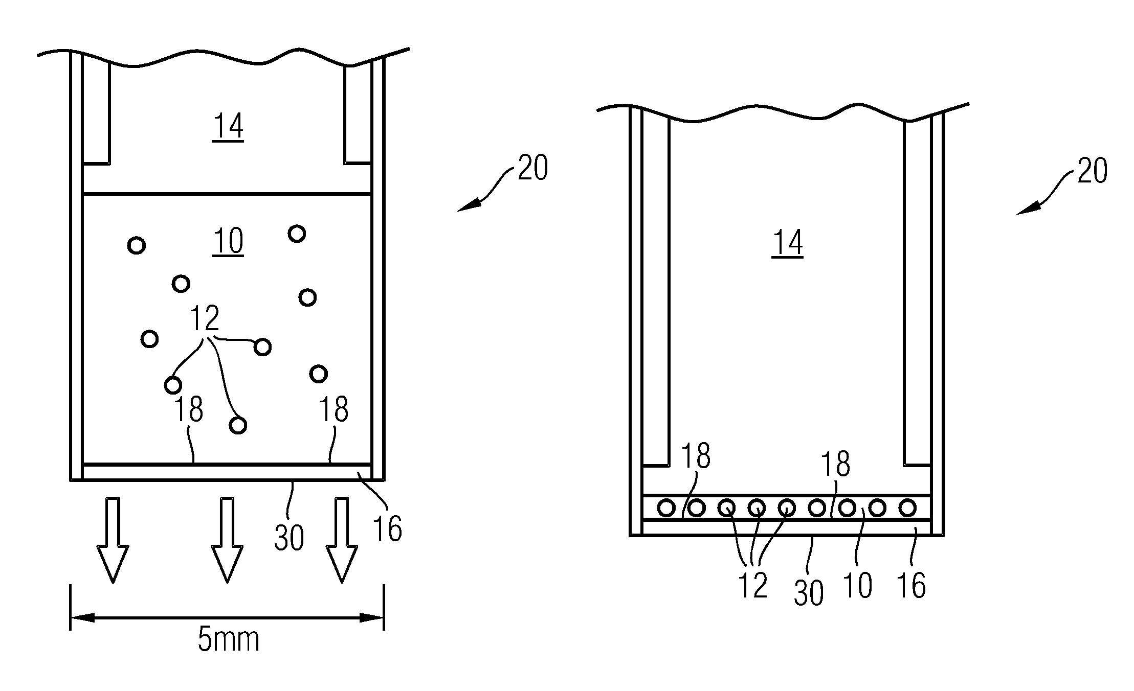
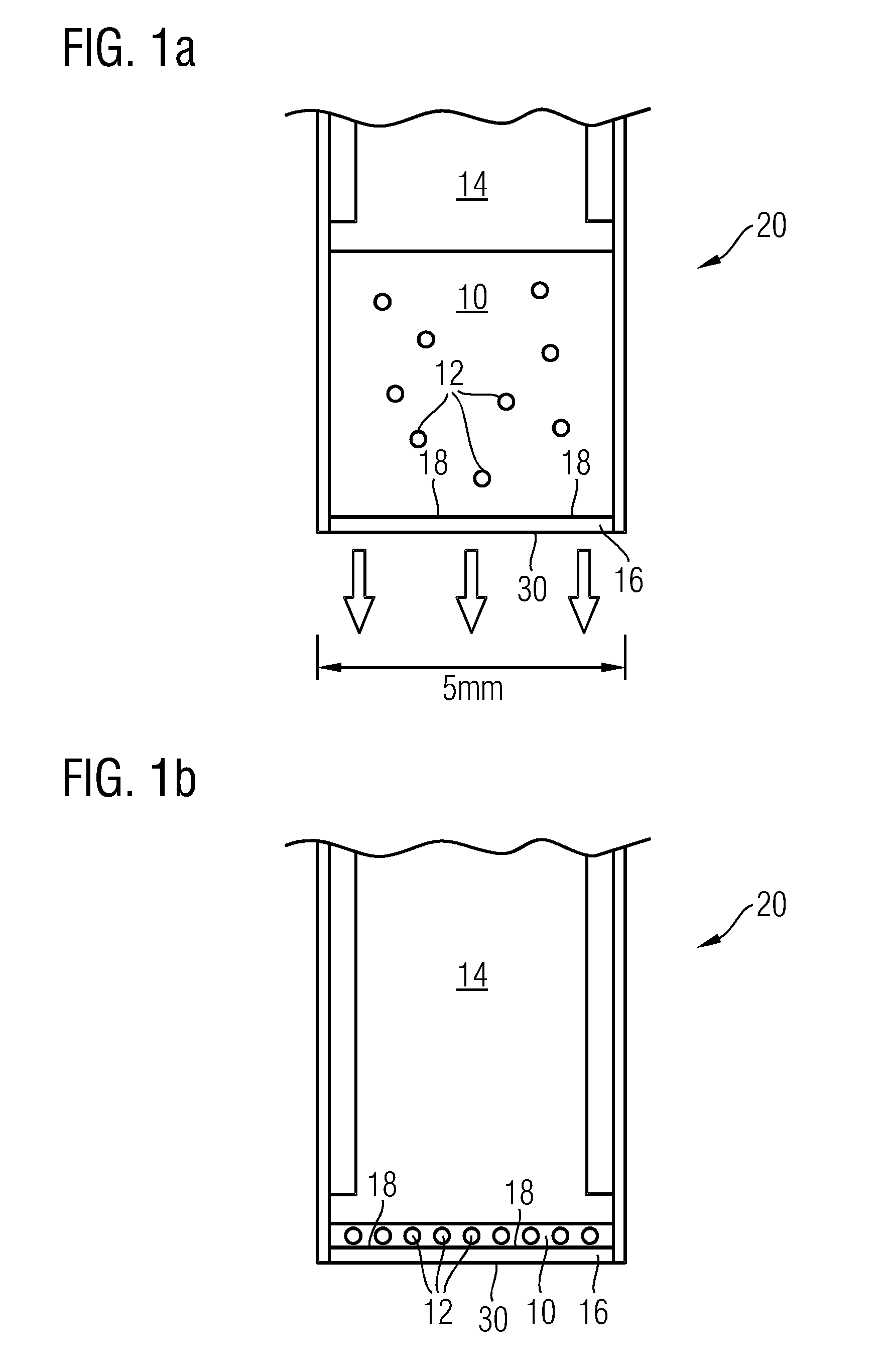
[0071]In a second embodiment the pumping direction is reversed after the first filtering step and a small part of the fluid and all retained micro-organisms are directed towards a small area filter.

third embodiment

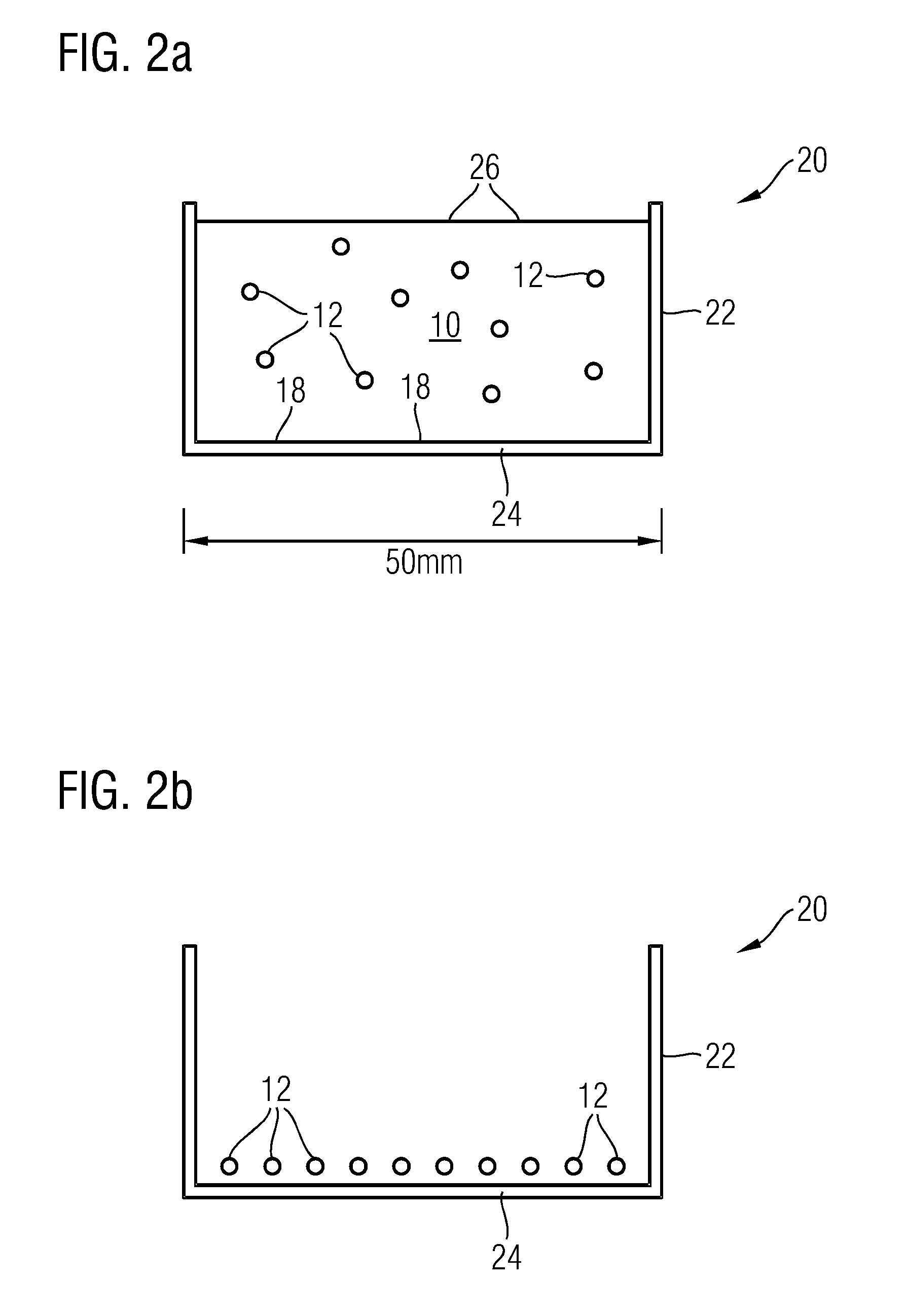
[0072]In a third embodiment a lateral flow is induced after the first filtering step such that the filter residue is collected onto a sub-area of the filter.

[0073]In all of these embodiments a dye, in particular a fluorescent dye, may be added to the fluid during the filtering, so that the micro-organisms are stained during the filtering steps. A preferred embodiment of this would be to include the dye in at least one of the filters. There are several methods for doing this:

[0074](a) Adding the dye as a coating to the filter. Upon exposing the filter to the to-be-analyzed liquid, the dye is released into the liquid.


PUM

PropertyMeasurementUnit
pore sizeaaaaaaaaaa
diameteraaaaaaaaaa
diameteraaaaaaaaaa

Abstract

A method of analyzing a sample fluid containing organic microobjects is proposed. The method comprises the steps of: up-concentrating (S1) the microobjects by removing, in a total time T1, a volume V1 of the sample fluid from the upconcentrate sample microobjects; immersing (S2) the microobjects in a transfer fluid, or leaving the microobjects in a remaining portion of the sample fluid, the remaining portion of the sample fluid then providing the transfer fluid; filtering (S3), in a total time T3, a volume V3 of the transfer fluid by a filter, thereby accumulating the microobjects on the filter; and generating (S4) an image of the microobjects accumulated on the filter; wherein the throughput V1 / T1 of the step of up-concentrating (S1) is greater than the throughput V1 / T1, of the step of filtering (S3). The filter may be a second filter, and the step of up-concentrating (S1) may involve: filtering the sample fluid by a first filter, thereby accumulating the microobjects on the first filter. An apparatus or system for analyzing a sample fluid containing organic microobjects is also disclosed.

Description

FIELD OF THE INVENTION[0001]In a first aspect, the invention relates to a method of analyzing a sample fluid containing organic microobjects.[0002]In a second aspect, the invention relates to an apparatus or system for analyzing a sample fluid containing organic microobjects.BACKGROUND OF THE INVENTION[0003]The invention relates to the field of microbiology, in particular to microbiological analysis of fluid samples. In general, such analysis is aimed at determining the presence / absence of specific organic microobjects in the sample, at quantifying their number or concentration, and in some cases at identifying an unknown microorganism to various levels of detail. The term “organic microobject” may refer to any object of a large variety of microscopic objects of biological origin, in particular microorganisms and cells. Microorganisms include bacteria, fungi, archaea, protists, green algae, animals such as plankton, the planarian and the amoeba. Cells include, apart from bacteria, p...

Claims


Application Information

Patent Timeline
Patent Type & Authority Patents(United States)
IPC IPC(8): G01N15/06G01N1/40
CPCG01N1/4077G01N1/4005G01N15/0625G01N15/0631
Inventor HULSKEN, BASKUIPER, STEINSTALLINGA, SJOERDISAKSSON, BO JOAKIMPONJEE, MARK W. G.VAN MEERBERGEN, BART E. G. J.UNAY, ZEYNEP S.
Owner KONINK PHILIPS ELECTRONICS NV
Features
  • R&D
  • Intellectual Property
  • Life Sciences
  • Materials
  • Tech Scout
  • Unparalleled Data Quality
  • Higher Quality Content
  • 60% Fewer Hallucinations
Learn More