
Image forming apparatus and image forming apparatus control method

a technology of image forming apparatus and control method, which is applied in the direction of electrographic process apparatus, digital output to print units, instruments, etc., can solve the problems of image quality, image cannot be transferred from the planned transfer start position of the paper, and the image cannot be transferred from the planned transfer start position, so as to reduce the waste of imag

Inactive Publication Date: 2015-09-08
KYOCERA DOCUMENT SOLUTIONS INC
View PDF7 Cites 0 Cited by
  • Summary
  • Abstract
  • Description
  • Claims
  • Application Information

AI Technical Summary

Benefits of technology

[0012]In view of the problem described above, it is an object of the present invention to, in a case where there is a possibility of a delay in paper arrival resulting in failure to perform transfer without any displacement from a transfer start position of paper, delay an image formation speed and an image data transmission speed to delay image arrival at a transfer part to thereby achieve transfer performed without any displacement, thus avoiding disposal of a temporarily-formed image due to the delay in the paper arrival and thereby reducing waste of the image.
[0014]According to this aspect, in a case where the paper arrival has not been detected at the check time point, the image formation speed and the image data transmission speed are delayed. Therefore, time of image arrival at the transfer part is delayed more than that in a case where the image formation is performed at a normal speed. That is, in accordance with the delay in the paper arrival, the image arrival at the transfer part is delayed, so that the image can be transferred without any displacement from the transfer start position of the paper. Moreover, the temporarily-formed image does not have to be disposed due to the delay in the paper arrival, avoiding unnecessary consumption of an image-forming material (for example, toner). Moreover, compared to a case where the image formation is performed again, overall time required for printing is shorter.

Problems solved by technology

However, due to factors such as a shift of a paper loading position at a paper storing portion, a change in a conveyance distance as a result of switching a paper cassette during continuous printing, slipping at a paper feed roller performing paper feeding and / or at a conveyance roller performing paper conveyance, paper arrival at the transfer part and the registration roller may be delayed.
As a result, there arises a case where the image is cut on the middle of the page or a case where a problem with image quality arises.
On the other hand, with the delay in the paper arrival at the transfer part and the registration roller, the image cannot be transferred from a planned transfer start position of the paper and thus displaced.
Moreover, with the delay in the paper arrival, the image may arrive at the transfer part earlier, with part thereof transferred onto a component inside the transfer part, which may stain later-arriving paper.
However, even when the period during which the paper is stopped at the registration roller is reduced to zero, the earlier the image arrives at the transfer part, the greater the delay in the paper arrival at the registration roller may be.
That is, there is a problem of limitations on coping with the delay in the paper arrival by reducing the period during which the paper is stopped at the registration roller.
However, the image disposal presents a problem that the already formed image is wasted and also longer time is required for printing.
However, a delay in the paper arrival to a degree over a time point (limit) that permits transfer without any displacement from the transfer start position of the paper may require the image disposal.
Therefore, there are some cases where the problem of limitation on coping with the delay in the paper arrival by reducing the period during which the paper is stopped at the registration roller cannot be coped with.

Method used


Image

  • Image forming apparatus and image forming apparatus control method
  • Image forming apparatus and image forming apparatus control method
  • Image forming apparatus and image forming apparatus control method

Examples


first embodiment

[0027]Hereinafter, with reference to FIGS. 1 to 7, the present invention will be described, referring to as an example a color multi-function printer 100 (corresponding to image forming apparatus) of a xerographic, tandem type. Note that factors such as configuration and arrangement described in this embodiment do not limit the scope of the invention and thus just serve as illustrative examples.

[0028](Outline of the Multi-function Printer 100)

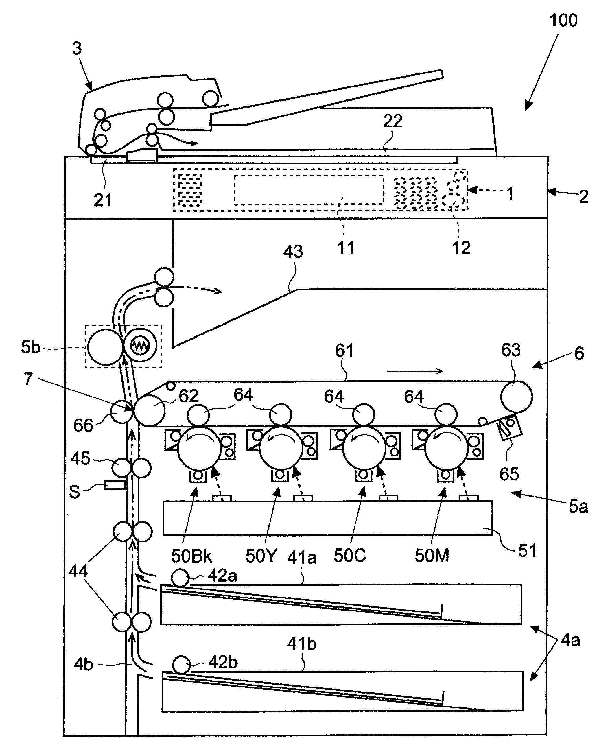
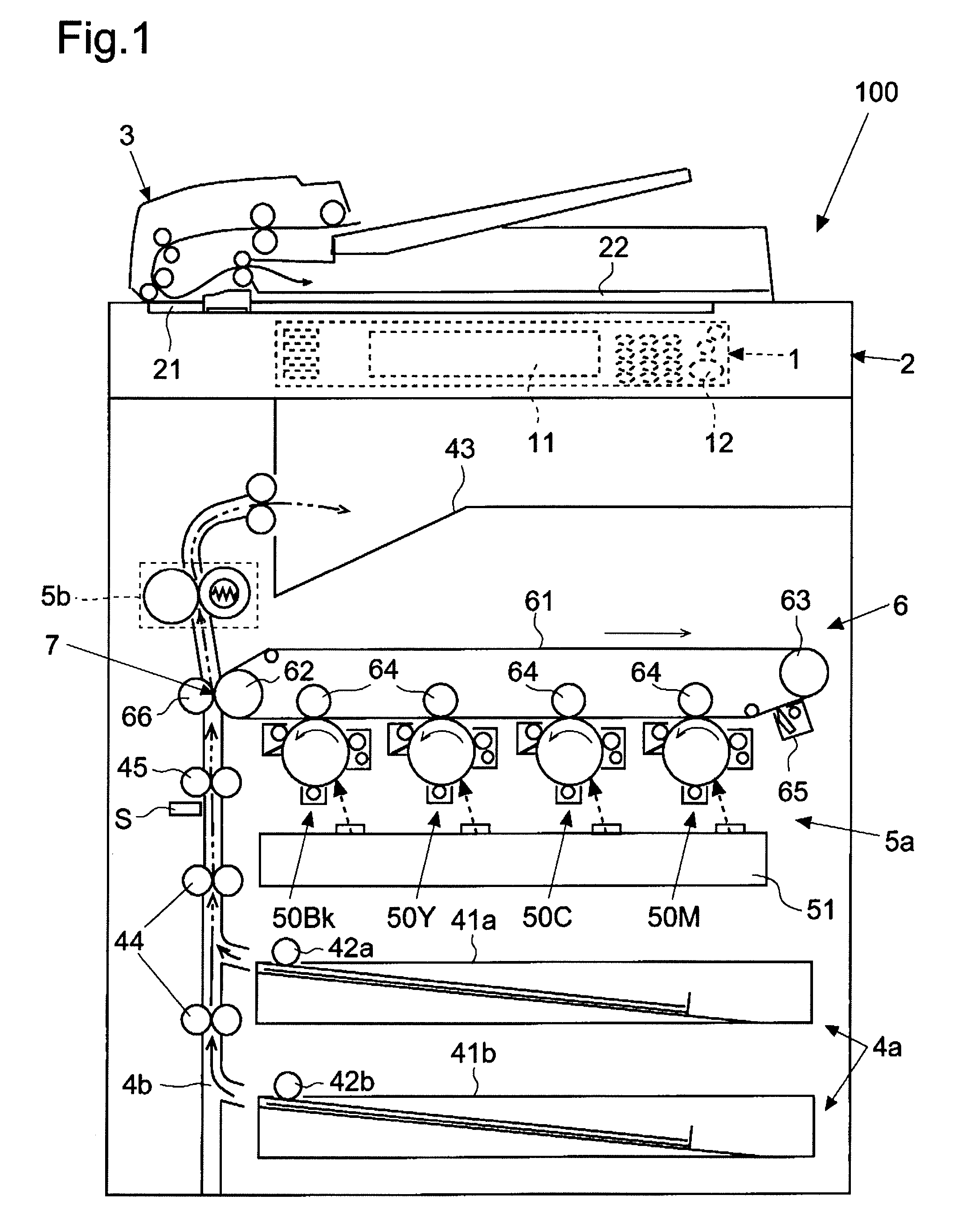
[0029]First, based on FIG. 1, outline of the multi-function printer 100 will be described. FIG. 1 is a schematic elevation sectional view of the multi-function printer 100 according to the first embodiment of the invention.

[0030]As shown in FIG. 1, arranged at the front of the multi-function printer 100 in an elevation view is an operation panel 1 for operation setup of the multi-function printer 100 (to be described in detail later). Moreover, provided on the top of the multi-function printer 100 are: an image reading part 2 reading an image o...

second embodiment

[0105](Second Embodiment)

[0106]Next, using FIGS. 3 and 8 to 11, a multi-function printer 100 according to the second embodiment of the invention will be described. Here, the multi-function printer 100 shown in second embodiment differs from that of the first embodiment in that, when paper arrival at a registration roller pair 45 has been delayed, without stopping image formation and image data transmission to an exposure device 51, an image formation speed and an image data transmission speed are decreased. Note that basic configuration of the multi-function printer 100 descried referring to FIGS. 1 to 3 is the same as that of the first embodiment. Therefore, for common portions, the description of the first embodiment applies, and thus only points different from those of the first embodiment will be described and illustrated below.

[0107](Hardware Configuration of the Multi-Function Printer 100)

[0108]First, referring to FIG. 3, hardware configuration of the multi-function printer 10...


PUM


Abstract

An image forming apparatus according to the present invention includes: a paper feed part; a conveying path conveying paper from the paper feed part; a transfer part transferring an image onto the paper; a registration roller timely delivering the paper to the transfer part; a paper detector detecting paper arrival at the registration roller; an image forming part starting image formation; an image processing part transmitting to the image forming part image data used for the image formation; and a control part, based on output of the paper detector, in a case where the paper detector has not detected the paper arrival at a check time point provided before a tip of the image arrives at the transfer part after the start of the image formation, delaying an image formation speed at the image forming part and an image data transmission speed of the image processing part.

Description

[0001]This application is based upon and claims the benefit of priority from the corresponding Japanese Patent Application No. 2009-150028 filed on Jun. 24, 2009, the entire contents of which are incorporated herein by reference.BACKGROUND OF THE INVENTION[0002]1. Field of the Invention[0003]The present invention relates to an image forming apparatus such as a copier, a multi-function printer, a printer, or the like that performs printing by previously forming images on image carriers and then transferring the formed images onto paper.[0004]2. Description of Related Art[0005]Typically, some of image forming apparatuses such as copiers, multi-function printers, and printers previously form an image (for example, toner image) on an image carrier. In such image forming apparatuses, for the purpose of synchronizing image delivery to a transfer part performing image transfer with paper arrival, a registration roller is provided. The registration roller timely enters paper into the transf...

Claims


Application Information

Patent Timeline
Patent Type & Authority Patents(United States)
IPC IPC(8): G06F3/12G03G15/00H04N1/04
CPCG03G15/6564
Inventor TAKAHASHI, TOMOHIRO
Owner KYOCERA DOCUMENT SOLUTIONS INC
Learn More