
Image forming apparatus, method of controlling the same, and computer-readable storage medium

Active Publication Date: 2015-09-15
CANON KK
View PDF6 Cites 2 Cited by
  • Summary
  • Abstract
  • Description
  • Claims
  • Application Information

AI Technical Summary

Benefits of technology

The patent describes a technique that allows for continued printing even if one of the paper feeding devices fails. This is achieved by using an alternative paper feeding apparatus that is not affected by the failure.

Problems solved by technology

In the conventional image forming apparatus, the entire apparatus enters an error state when the failure is detected, and the use of the apparatus becomes impossible.
In this case, although the other paper feeding apparatuses are not broken down, the apparatus cannot be used until the paper feeding apparatus with the failure is repaired, and there is a problem that the work efficiency is reduced.

Method used


Image

  • Image forming apparatus, method of controlling the same, and computer-readable storage medium
  • Image forming apparatus, method of controlling the same, and computer-readable storage medium
  • Image forming apparatus, method of controlling the same, and computer-readable storage medium

Examples


first embodiment

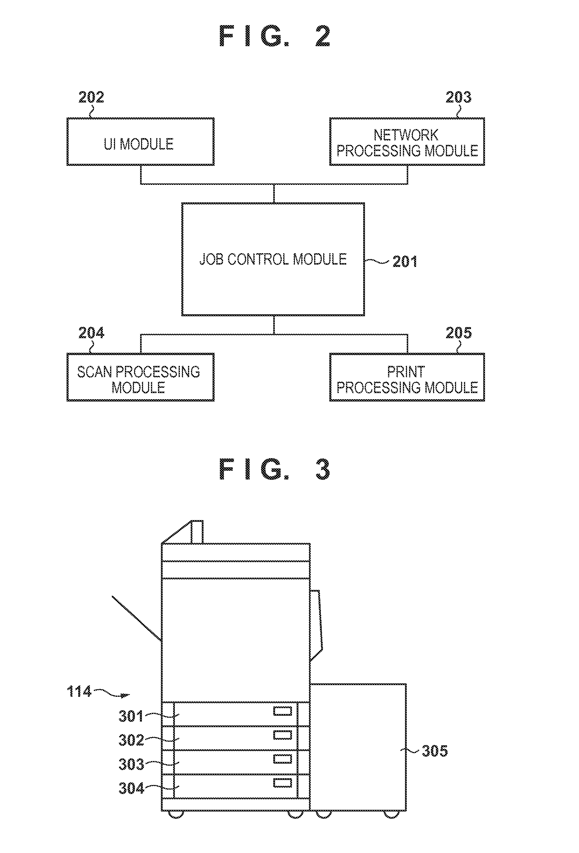
[0033]Operation when there is a failure in a paper feeding apparatus possessed by the printer 114 of the image forming apparatus according to a first embodiment will be described.

[0034]FIG. 4 is a flowchart for describing a process when a paper feeding apparatus detects a failure in the image forming apparatus according to the first embodiment of the present invention. The CPU 101 executes a program deployed from the HDD 104 into the RAM 102 to attain the process illustrated in the flow chart.

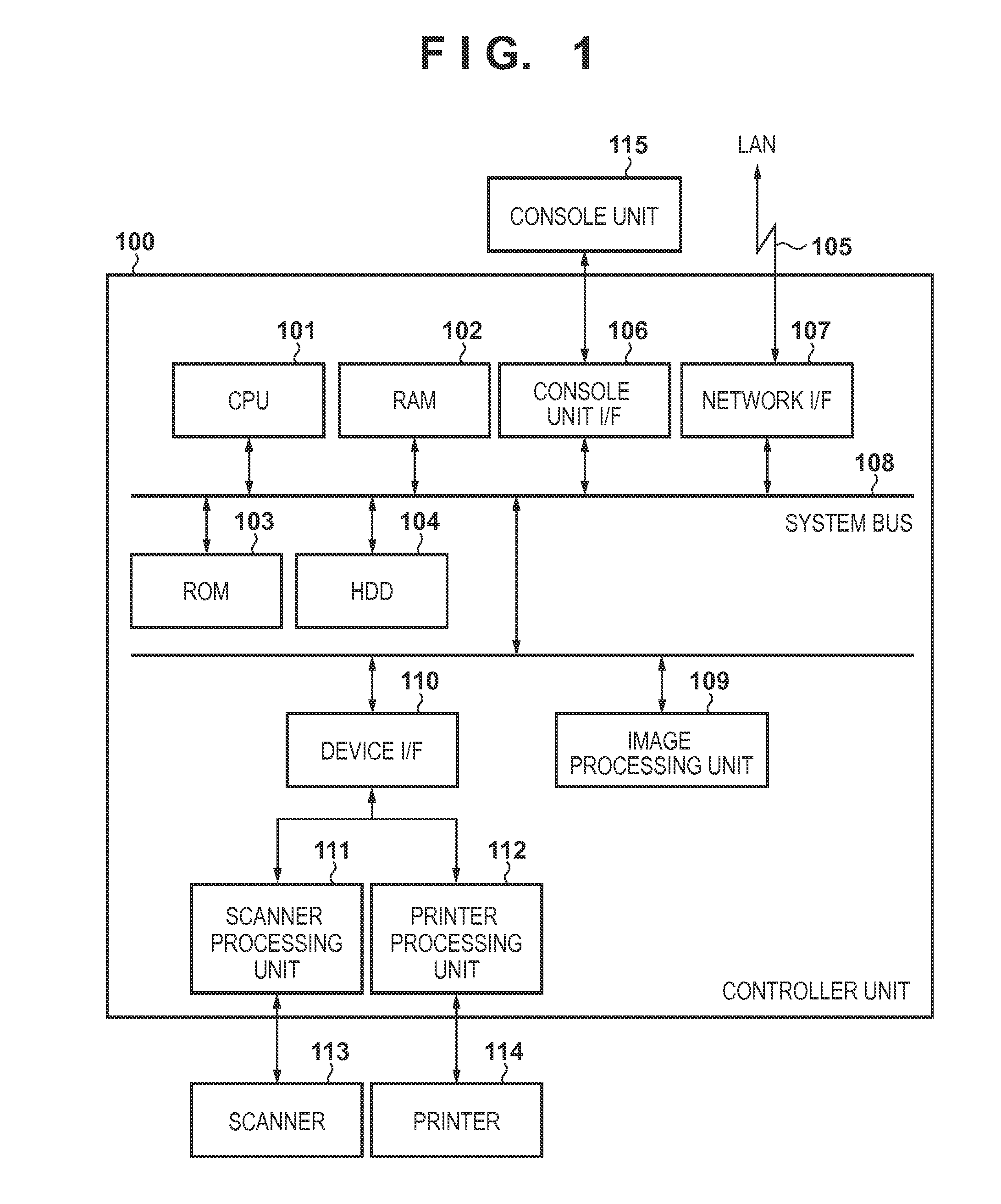
[0035]In step S401, the CPU 101 obtains information of the paper feeding apparatus through the printer processing unit 112 and the device I / F 110. The CPU 101 proceeds to step S402 and stores the obtained information in the RAM 102. The CPU 101 proceeds to step S403 and determines whether the obtained information includes information of a failure of the paper feeding apparatus. The failure of the paper feeding apparatus includes a case in which the paper does not reach a conveyable position whe...

second embodiment

[0049]In the first embodiment, an example of limiting the selection of the paper feeding apparatus on the screen displayed on the console unit 115 when a failure of the paper feeding apparatus is detected is described. In a second embodiment, operation of automatic paper selection when a failure of a paper feeding apparatus is detected will be described. The hardware configuration of the image forming apparatus according to the second embodiment is the same as that of the first embodiment, and the description will not be repeated.

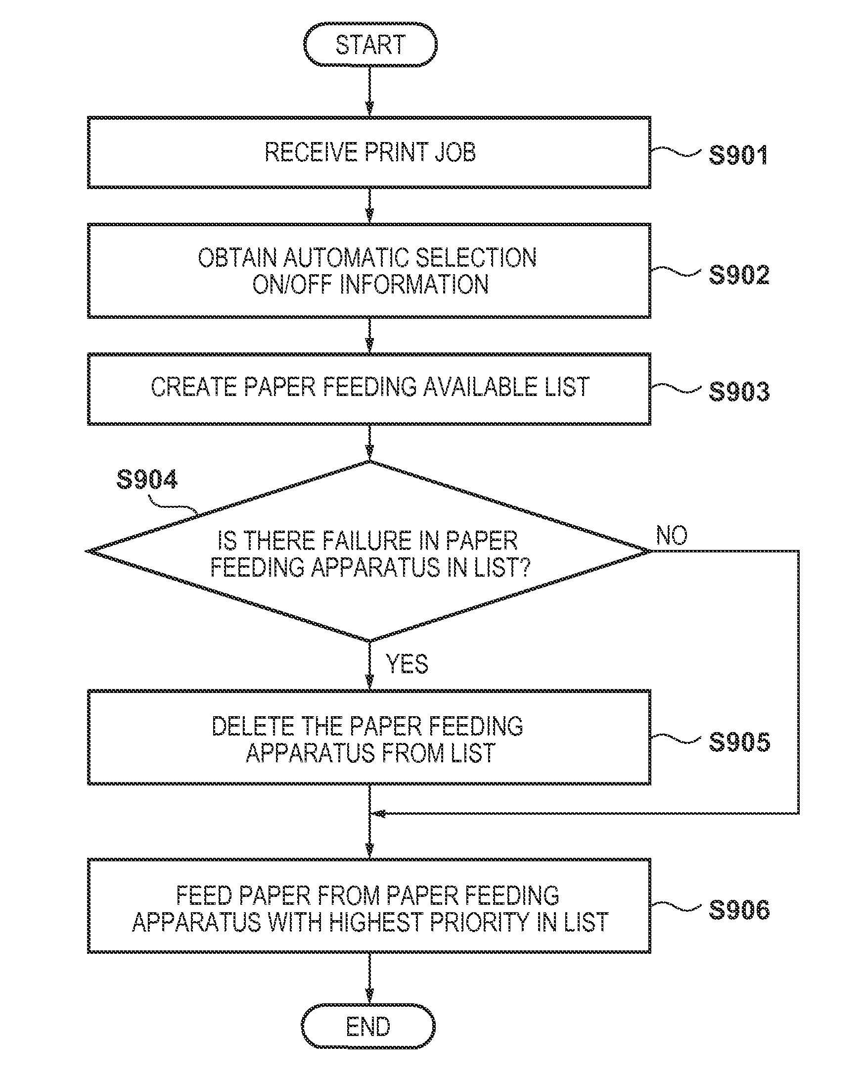
[0050]FIG. 9 is a flowchart for describing a selection process of a paper feeding apparatus used in printing when a failure is detected in a paper feeding apparatus in the image forming apparatus according to the second embodiment of the present invention. The CPU 101 executes a program deployed from the HDD 104 into the RAM 102 to attain the process illustrated in the flow chart.

[0051]In step S901, the CPU 101 receives a print job. The CPU 101 proceeds to ...


PUM


Abstract

An image forming apparatus including a plurality of paper feeding units and a method of controlling the same are provided, wherein out-of-paper in at least one of the plurality of paper feeding units is detected, and a failure in at least one of the plurality of paper feeding units is detected. The apparatus controls to permit selecting a paper feeding unit to be used as a paper feeding source of paper in which the out-of-paper is detected, and the apparatus controls not to permit selecting the paper feeding unit in which the failure is detected.

Description

BACKGROUND OF THE INVENTION[0001]1. Field of the Invention[0002]The present invention relates to an image forming apparatus, a method of controlling the same, and a computer-readable storage medium.[0003]2. Description of the Related Art[0004]A conventional image forming apparatus includes at least one or more paper feeding apparatuses that store paper, such as paper feeding cassettes and paper feeding decks. For example, Japanese Patent Laid-Open No. 2008-030451 discloses an image forming apparatus including two cassettes and one deck as paper feeding apparatuses. In the image forming apparatus including the plurality of paper feeding apparatuses, the paper feeding apparatus to be used for printing can be allocated for jobs, such as copying, a print job from a printer driver, and reception of FAX.[0005]In the image forming apparatus, there is a case in which part of the paper feeding apparatuses breaks down due to a failure of a roller or the like. In the conventional image forming...

Claims


Application Information

Patent Timeline
IPC IPC(8): B41J29/393B41J29/38B41J13/00
CPCB41J29/38B41J13/0009B41J11/0075B41J13/0018
Inventor MUTSUNO, MASAHIRO
Owner CANON KK
Learn More