Truck headache rack

a rack and truck head technology, applied in the field of truck headache racks, can solve the problems of one size not fitting all trucks, lack of lateral adjustment, etc., and achieve the effects of adding structural rigidity, enhancing visibility, and adding even more rigidity and load-carrying capability

Active Publication Date: 2015-09-15
WERNER CO
View PDF3 Cites 20 Cited by
  • Summary
  • Abstract
  • Description
  • Claims
  • Application Information

AI Technical Summary

Benefits of technology

[0007]In addition to its lateral adjustment capability, the headache rack of this invention adds structural rigidity to the connection between the upright side rails and the cross bar, and protects occupants of the vehicle from loads carried on the rack. A space may be provided between the top of the center panel and cross bar of the headache rack which aligns with the rear view minor of the truck for enhanced visibility. Further, a second headache rack may be positioned near the tailgate of the truck bed to add even more rigidity and load-carrying capability to the rack system.

Problems solved by technology

A common problem with vehicle rack systems generally, and headache racks in particular, is their lack of adjustability in the lateral direction, i.e. in the direction between the side walls of the truck bed.
One size does not fit all trucks.
While it is possible to fabricate headache racks for truck beds of any given width, that is impractical because retailers do not have the space to inventory or display a large number of different size racks.

Method used


Image

  • Truck headache rack
  • Truck headache rack
  • Truck headache rack

Examples


Embodiment Construction

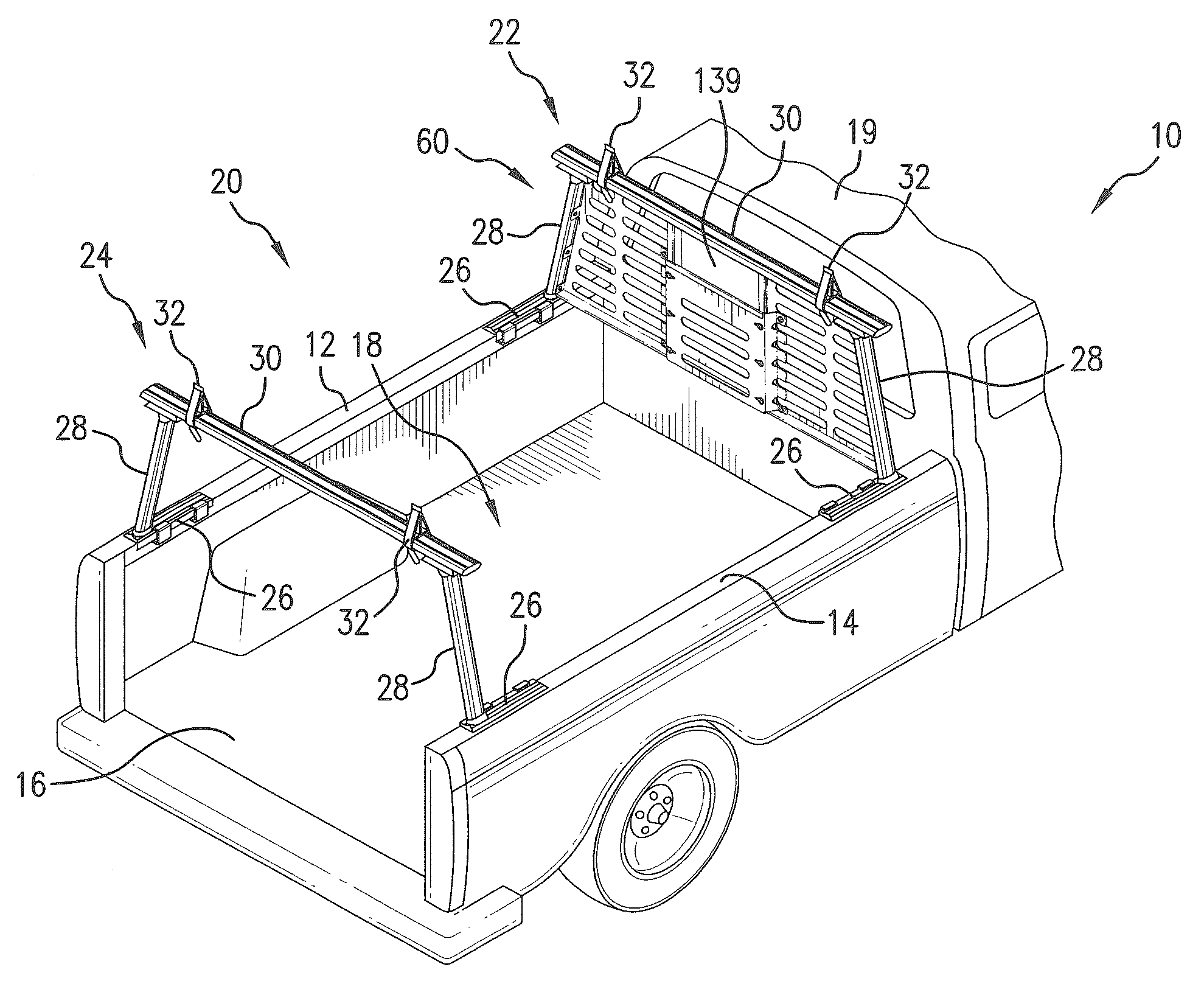
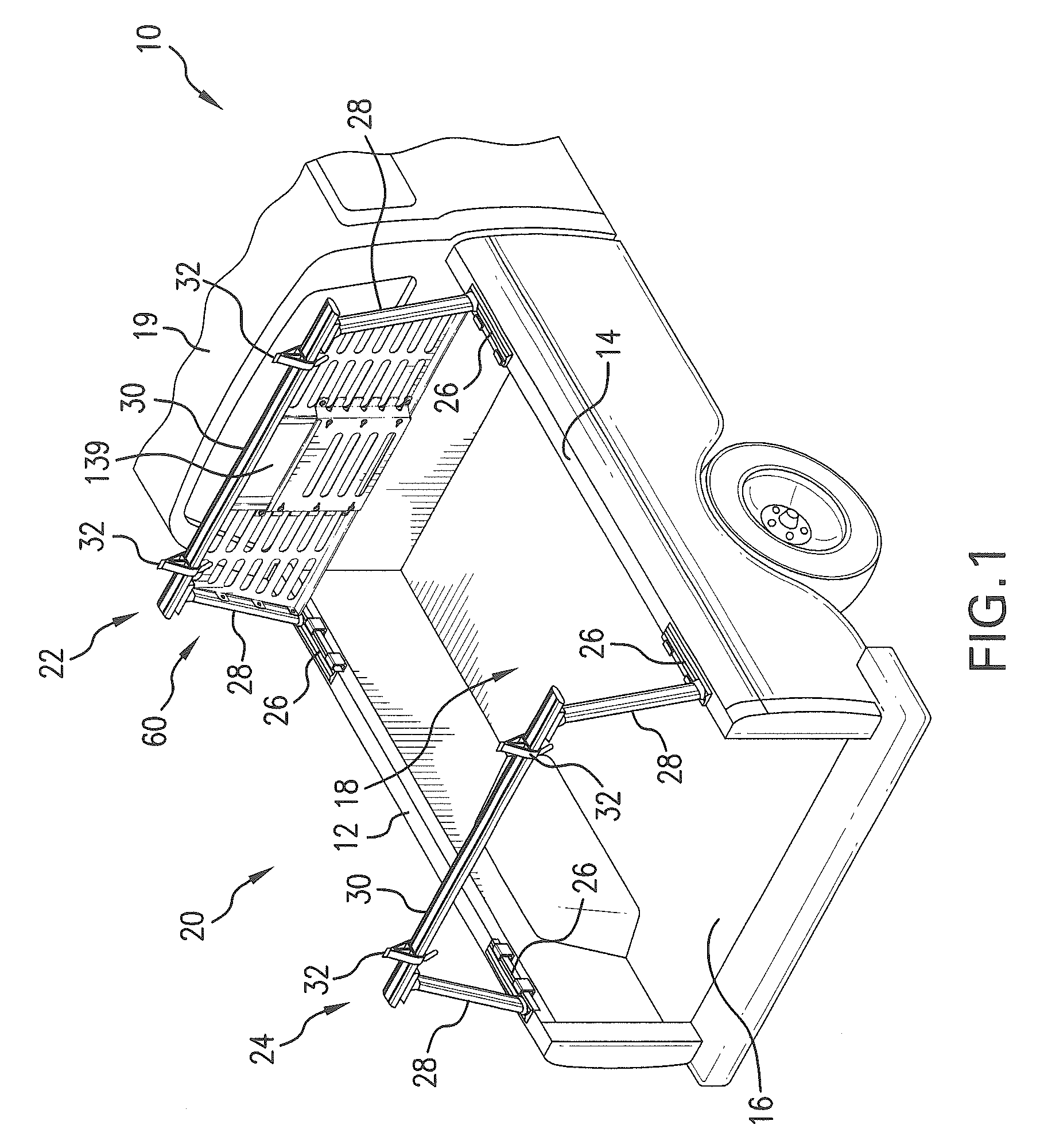
[0020]Referring initially to the FIG. 1, a pickup truck 10 is schematically depicted having a side wall 12, an opposed side wall 14 and a floor 16 between them which collectively define a bed 18 located behind the cab 19. The terms “front” and “forward” when used herein refer to a location proximate the cab 19 of the truck 10, whereas the terms “rear” and “rearward” denote the opposite end of the bed 18. The terms “lateral” and “laterally spaced” refer to a direction between the side walls 12, 14 of the truck bed 18.

[0021]A rack system 20 is illustrated in FIG. 1, which may be employed as a ladder rack for supporting elongated tools, equipment and / or materials, having a forward rack structure 22 and a rear rack structure 24. Each rack structure 22, 24 includes a base support 26 located on the side wall 12 of the truck 10, and a second base support 26 located on the opposite side wall 14 in substantial alignment with the first base support 26. Each base support 26 mounts an upright s...


PUM


Abstract

A headache rack for pickup trucks and similar vehicles is disclosed which comprises a three panel construction including a center panel connected between left and right side panels. Each of the left and right side panels is mounted to an upright side rail coupled to one of the side walls of the truck bed, and to a cross bar extending generally horizontally between the side rails. Adjustment structure is provided to adjust the overall lateral dimension of the three panels in order to accommodate truck beds of different width.

Description

FIELD OF THE INVENTION[0001]This invention relates to a rack system for vehicles, and, more particularly, to a headache rack for pickup trucks which is adjustable to accommodate vehicles having beds of different lateral dimension.BACKGROUND OF THE INVENTION[0002]Rack systems for mounting ladders, equipment and other loads to the bed of pickup trucks and similar vehicles are well known in the prior art. Most systems of this type generally comprise a framework of four or more upright side rails, two of which are mounted atop or alongside one of the side walls of the truck with the other two located on the opposite side wall. Cross bars are connected between aligning side rails on opposite side walls so that they span the bed of the truck in position to support equipment, materials or other loads in an elevated position above the truck bed.[0003]Headache racks may comprise or form part of rack systems of the type described above. Typically, headache racks include structure located in b...

Claims


Application Information

Patent Timeline
Patent Type & Authority Patents(United States)
IPC IPC(8): B60R9/06B60R21/02B62D33/02B60R21/00
CPCB60R9/06B60R21/02B62D33/02B60R2021/0083B60R9/045
Inventor HARRISON, CRAIG
Owner WERNER CO
Why Eureka
Try Eureka