
Illuminating module for a motor vehicle

a technology for illumination modules and motor vehicles, applied in fixed installation, light and heating equipment, transportation and packaging, etc., can solve the problems of insufficient efficiency of such a module and the inability to generate satisfactory intensity light beams using limited optical resources, and achieve the effect of optimizing the transmission efficiency of optical beams and increasing efficiency

Active Publication Date: 2015-09-15
VALEO VISION SA
View PDF10 Cites 6 Cited by
  • Summary
  • Abstract
  • Description
  • Claims
  • Application Information

AI Technical Summary

Benefits of technology

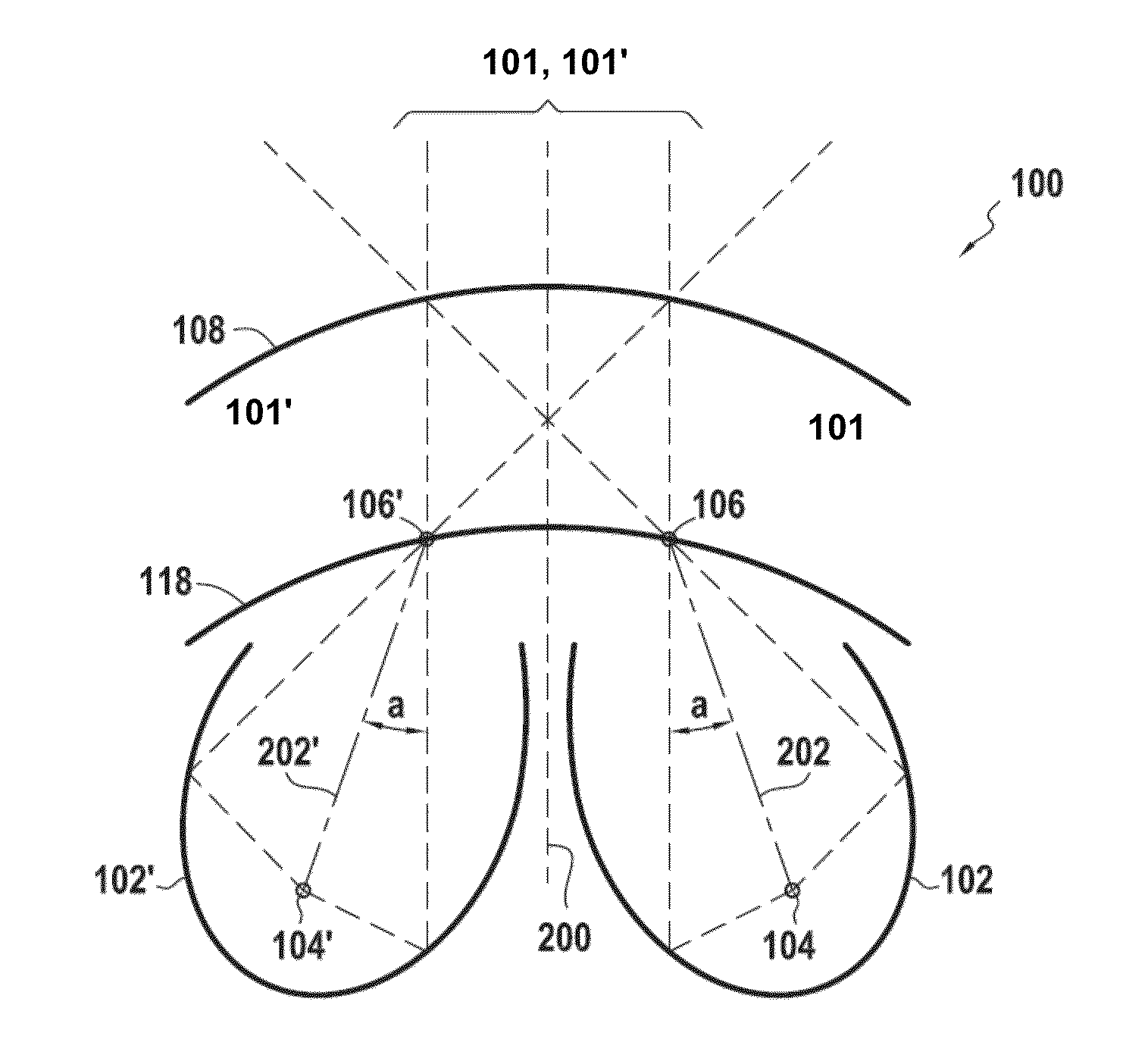
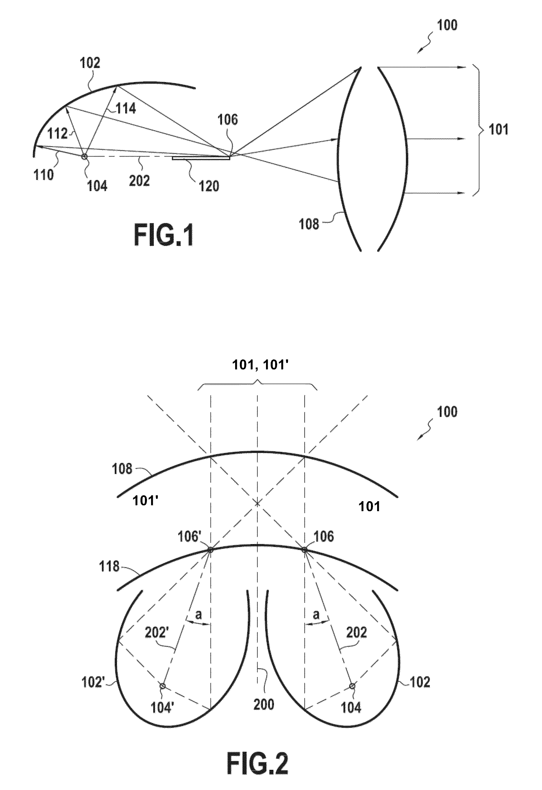
[0010]The present invention aims to solve at least one of these problems. The invention results from an observation specific to the invention, according to which, in order to optimize the transmission efficiency of the optical beam generated by a source, the latter should be placed at the focal point of a convergent reflector in order for the maximum amount of optical radiation emitted by the source to be collected by this reflector and transmitted to an output lens of the module. Specifically, a so-called “convergent” reflector makes the reflected light rays converge, and therefore has a higher efficiency.
[0013]Such a module has many advantages. In particular it employs reflectors that collect a large part of the optical radiation emitted by the light sources located at their focal points. By concentrating this radiation to a point of focus before transmitting it through the output lens, such a module makes it possible to generate illuminating lights, typically fog lights, with two sources of limited power, for example two light-emitting diodes with powers of 3 W or less.
[0014]Moreover, such a module allows a single beam having a particularly satisfactory uniformity to be formed from a plurality of beams. In fact, such a single beam exhibits a uniform decrease in its brightness from a central portion, thereby improving the comfort of the driver and passenger of a vehicle equipped with such a module.

Problems solved by technology

Therefore the intensity of the beam does not decrease uniformly from a maximum intensity level at the center of the beam.
In addition, the efficiency of such a module is insufficient to enable a light beam to be generated with a satisfactory intensity using optical resources limited, for example, to two 3 W light-emitting diodes.
This is due to the fact that the reflectors are relatively open and do not allow a maximal amount of flux to be collected.

Method used


Image

  • Illuminating module for a motor vehicle
  • Illuminating module for a motor vehicle
  • Illuminating module for a motor vehicle

Examples


Embodiment Construction

[0030]In the present description, identical elements or elements having similar functions may be referenced with the same reference number in the various figures.

[0031]The embodiment of an illuminating module 100 for a motor vehicle lamp according to the invention, i.e. able to form a wide light beam 101 containing a cutoff, is now described with reference to FIGS. 1 and 2. A beam 101 is considered to be a wide beam 101 when it has a total lateral aperture lying between 40 degrees and 100 degrees, or even a half-aperture, with reference to the longitudinal axis of symmetry of the vehicle, lying between 25 degrees and 50 degrees, the aperture (or the half-aperture) being defined for a minimum intensity of about 100 candelas.

[0032]More precisely, FIGS. 1 and 2 show vertical and horizontal cross-sectional views, respectively, of such a module 100, cut through a reflector 102, these sections being cut in vertical and horizontal planes that pass through the source 104 and the point of fo...


PUM

PropertyMeasurementUnit
powersaaaaaaaaaa
focal lengthaaaaaaaaaa
depthaaaaaaaaaa

Abstract

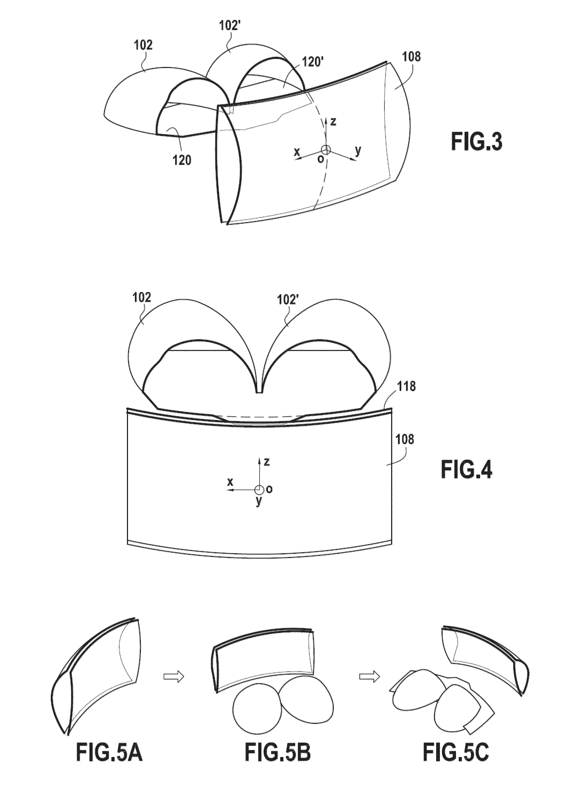
An illuminating module for a motor vehicle lamp able to form a wide light beam containing a cutoff, which module is equipped with optical elements comprising an output lens and a plurality of concave reflectors associated with a deflector having a reflective face intended to deflect light beams generated by light sources located in the concavities of the reflectors. The output lens is a toric lens, and these optical elements are arranged in order to make the light beams generated by said light sources converge on points of focus before these light beams are transmitted through the output lens. The module comprises two reflectors (102, 102′) oriented toward each other.

Description

CROSS-REFERENCE TO RELATED APPLICATIONS[0001]This application claims priority to French Application No. 1258683 filed Sep. 17, 2012.BACKGROUND OF THE INVENTION[0002]1. Field of the Invention[0003]The invention relates to an illuminating module for a motor vehicle, especially intended to generate a wide cutoff-containing optical beam from a plurality of light sources.[0004]2. Description of the Related Art[0005]It is known practice to form an illuminating module for a motor vehicle with a plurality of concave reflectors, each comprising a light source in its concavity, in order to combine the light beams obtained from each reflector and form an optical beam.[0006]By way of example, document EP 1 610 057 B1, which is equivalent to U.S. Publication No. 2006 / 0002130 and U.S. Pat. No. 7,682,057, describes such a module equipped with three reflectors such that the edges of the reflectors are placed one against the other. The beams obtained from these reflectors are then combined in such a...

Claims


Application Information

Patent Timeline
Patent Type & Authority Patents(United States)
IPC IPC(8): F21S8/10
CPCF21S48/1208F21S48/1266F21S48/1388F21S48/1159Y10T29/49002F21S41/148F21S41/26F21S41/321F21S41/33F21S41/365F21S41/43F21S41/29
Inventor DE LAMBERTERIE, ANTOINETHABET, ZIYED
Owner VALEO VISION SA
Learn More