Vibrating mirror element, distance measuring apparatus, and projector
a technology of mirror element and rotating mirror, which is applied in the direction of distance measurement, instruments, surveying and navigation, etc., can solve the disadvantageous limitation of the time when the turning angle velocity of the first movable element can be substantially constant, and achieve the effect of easy oscillation and easy formation
- Summary
- Abstract
- Description
- Claims
- Application Information
AI Technical Summary
Benefits of technology
Problems solved by technology
Method used
Image
Examples
first embodiment
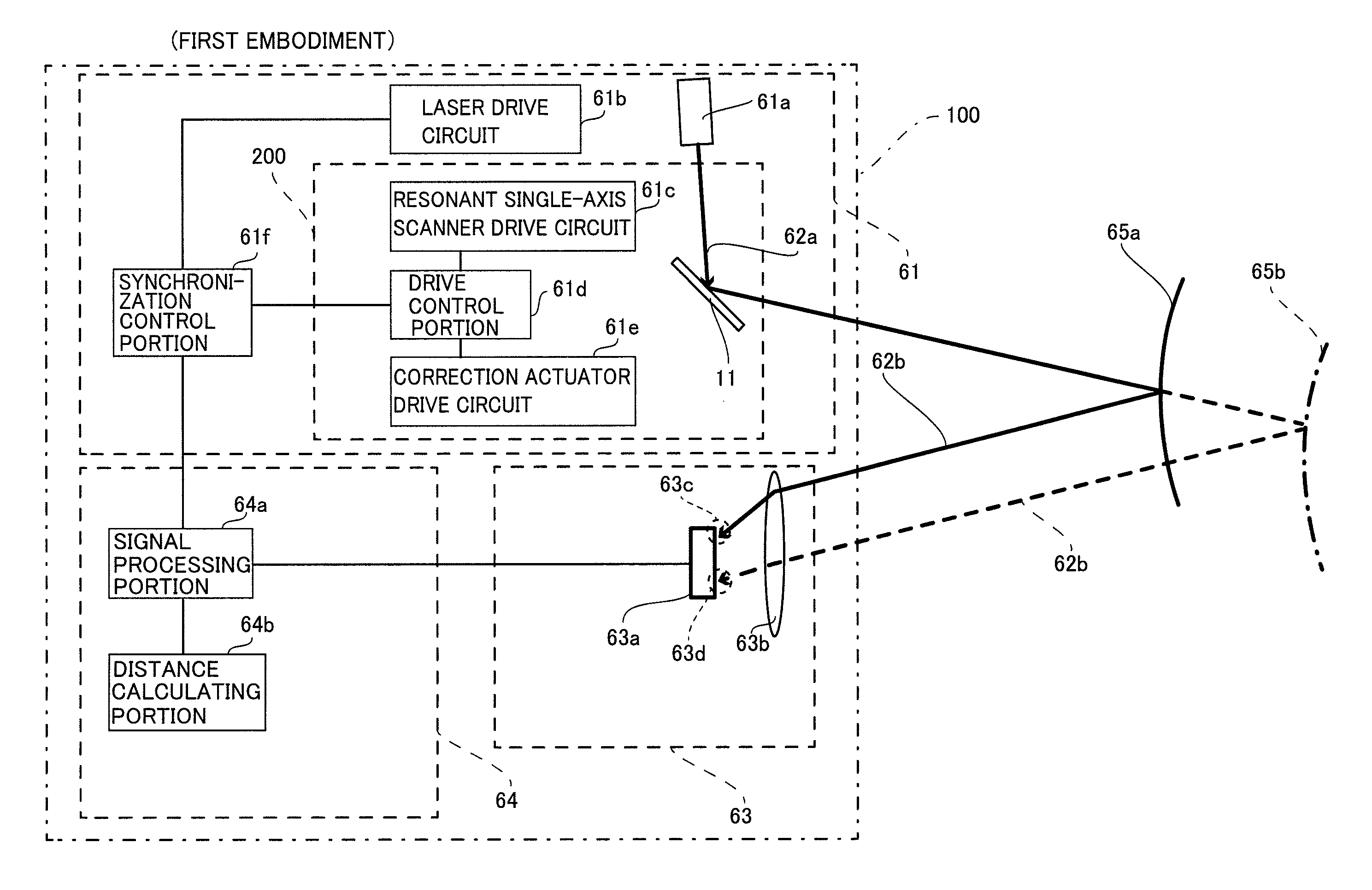
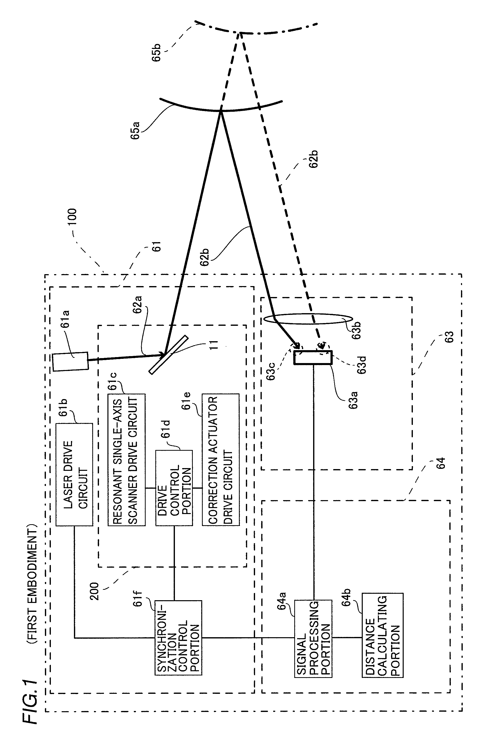
[0046]The structure of a distance measuring apparatus 100 according to a first embodiment of the present invention is now described with reference to FIGS. 1 to 6.
[0047]The distance measuring apparatus 100 according to the first embodiment of the present invention includes a light emitting portion 61, a light receiving portion 63 receiving laser light 62a emitted from the light emitting portion 61 and reflected by an measurement object 65a, and a distance measuring portion 64 acquiring a distance from the measurement object 65a on the basis of the detection result of the light receiving portion 63, as shown in FIG. 1.
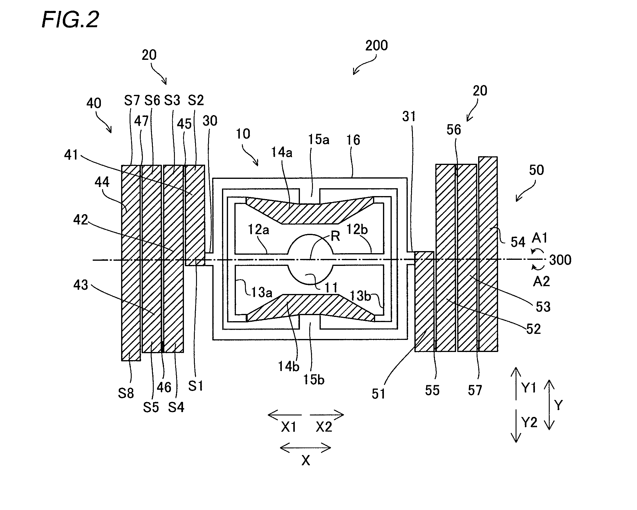
[0048]The light emitting portion 61 includes a CW (continuous wave) laser light source 61a emitting the laser light 62a of an infrared wavelength region, a laser drive circuit 61b configured to drive the CW laser light source 61a, a vibrating mirror element 200 configured to deflect the laser light 62a emitted from the CW laser light source 61a, and a synchronization co...
second embodiment
[0087]The structure of a distance measuring apparatus 101 according to a second embodiment is now described with reference to FIG. 7. According to the second embodiment, the distance measuring apparatus 101 is configured to include a short-pulse laser light source and a distance measuring portion detecting light receiving time information by a light receiving portion, calculating a distance between the distance measuring apparatus and a measurement object from the detection result, unlike the aforementioned distance measuring apparatus 100 according to the first embodiment configured to include the CW laser light source and the distance measuring portion detecting light receiving position information, calculating the distance between the distance measuring apparatus and the measurement object from the detection result.
[0088]As shown in FIG. 7, the distance measuring apparatus 101 includes a light emitting portion 61g, a light receiving portion 63e receiving short-pulse laser light 6...
third embodiment
[0093]The structure of a projector 102 according to a third embodiment is now described with reference to FIG. 8. In the third embodiment, the vibrating mirror element according to the present invention is applied to the projector, unlike in each of the aforementioned first and second embodiments in which the vibrating mirror element according to the present invention is applied to the distance measuring apparatus.
[0094]As shown in FIG. 8, no light receiving portion 63 or distance measuring portion 64 is provided in the projector 102 according to the third embodiment, unlike in the aforementioned first embodiment. According to the third embodiment, a vibrating mirror element 201 includes at least two vibrating mirror elements 200 or is configured to be biaxially driven in order to deflect laser light 62a in a planar direction (an X-axis or Y-axis direction). The remaining structure of the projector 102 according to the third embodiment is similar to that of the distance measuring ap...
PUM
 Abstract
Description
Claims
Application Information
 - R&D
- Intellectual Property
- Life Sciences
- Materials
- Tech Scout
- Unparalleled Data Quality
- Higher Quality Content
- 60% Fewer Hallucinations
Browse by: Latest US Patents, China's latest patents, Technical Efficacy Thesaurus, Application Domain, Technology Topic, Popular Technical Reports.
© 2025 PatSnap. All rights reserved.Legal|Privacy policy|Modern Slavery Act Transparency Statement|Sitemap|About US| Contact US: help@patsnap.com


