Predictive focusing for image scanning systems

a technology of image scanning and predictive focusing, applied in the field of predictive focusing in image scanning systems, can solve the problems of image blurring and inevitable increase in implementation costs

Active Publication Date: 2015-09-15
HONG KONG APPLIED SCI & TECH RES INST
View PDF5 Cites 0 Cited by
  • Summary
  • Abstract
  • Description
  • Claims
  • Application Information

AI Technical Summary

Benefits of technology

[0012]Optionally, the central region is configured to provide a substantially constant change in optical path length across the central region when second plural light beams travel into the central region in a direction along the optical axis. The central region is additionally configured such that a second image formed by the second plural light beams has a focus plane that is optically adjustable by a focusing mechanism of the apparatus to coincide with the imaging sensor, thereby allowing the second image to be in-focus captured by the imaging sensor.
[0020]Comprising the predictive-focusing apparatus as disclosed, preferably the image scanning system further comprises a primary sensor for imaging the image appeared on the current imaging FoV. The primary sensor has one or more advantages over the imaging sensor in capturing the image appeared on the current imaging FoV. Such one or more advantages include one or more of the following items: higher imaging resolution; controllable imaging resolution; higher light sensitivity; lower imaging noise level; and higher spectral sensitivity over a dedicated range of wavelengths.

Problems solved by technology

These lenses have very shallow depths of view so that a slight sample-surface roughness or stage tilt can lead to image blurring.
However, the implementation cost is inevitably increased.

Method used


Image

  • Predictive focusing for image scanning systems
  • Predictive focusing for image scanning systems
  • Predictive focusing for image scanning systems

Examples


Embodiment Construction

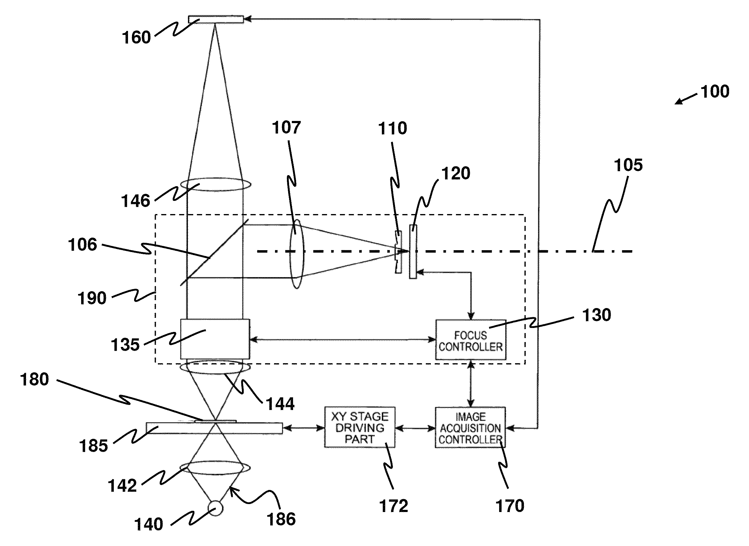
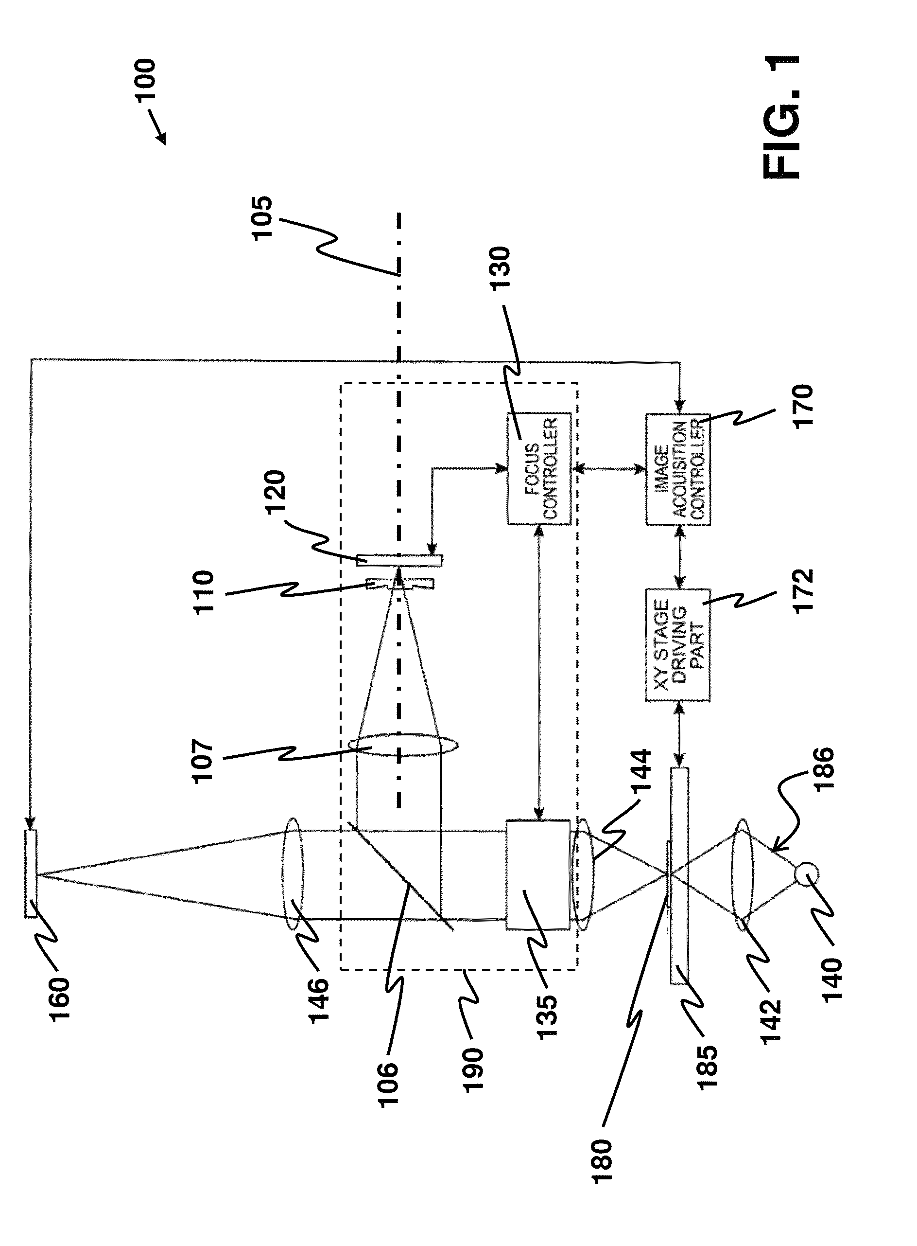
[0033]An aspect of the present invention is to provide an apparatus for achieving predictive focusing in an image scanning system. The image scanning system is configured to scan a sample by partitioning the sample into an array of FoVs. Focusing is individually applied to each of the FoVs, and the array of FoVs, arranged as rows of FoVs, is scanned in a raster-scanning manner. FIG. 1 depicts an image scanning system that comprises an embodiment of the disclosed apparatus.

[0034]An image scanning system 100 is configured to scan a sample 180 that is placed on a specimen holder 185. The specimen holder 185 is driven by a holder driver 172 so as to move the sample 180 in a raster-scanning manner and allow a FoV on the sample 180 to be precisely positioned for imaging. The FoV is illuminated by a probe light beam 186 generated by using a condenser lens 142 to concentrate light beams generated from a light source 140. After passing through the FoV, the probe light beam 186 carries an ima...


PUM


Abstract

This invention discloses an apparatus for achieving predictive focusing in an image scanning system. The apparatus comprises an optical path-length changing plate and an image sensor. In one embodiment, the plate comprises a plurality of path-length changing members. The plate further includes a central region configured to provide a substantially constant change in optical path length across the central region, allowing an image passing therethrough to be in-focus captured. Having a light receiving surface, each path-length changing member is configured to provide a substantially non-uniform change in optical path length across the light receiving surface, allowing a focus plane of the image to be tilted such that the image projected onto the imaging sensor can be used for predicting an amount of optical adjustment required to achieve focusing. By using more than one path-length changing member, predictive focusing is achievable with more than one direction of focus-plane tilting.

Description

COPYRIGHT NOTICE[0001]A portion of the disclosure of this patent document contains material, which is subject to copyright protection. The copyright owner has no objection to the facsimile reproduction by anyone of the patent document or the patent disclosure, as it appears in the Patent and Trademark Office patent file or records, but otherwise reserves all copyright rights whatsoever.FIELD OF THE INVENTION[0002]The present invention relates to an apparatus for achieving predictive focusing in an image scanning system. The image scanning system, such as a microscope system, is configured to raster-scan a sample where the sample is partitioned into an array of fields of view.BACKGROUND[0003]In some practical imaging applications, it is desired to scan a sample by partitioning the sample into an array of fields of view (FoVs) and scanning the array of FoVs in a raster-scanning manner. Before an image appeared on one FoV is captured, focusing is performed in order to bring this image ...

Claims


Application Information

Patent Timeline
Patent Type & Authority Patents(United States)
IPC IPC(8): G02B21/36G02B21/02
CPCG02B21/361G02B21/025
Inventor WU, XIAOHUA
Owner HONG KONG APPLIED SCI & TECH RES INST
Why Eureka
Try Eureka