

Method of manufacturing an optical display
a manufacturing method and optical display technology, applied in the direction of thin material processing, instruments, construction, etc., can solve the problem of a large amount of oil required in the method, and achieve the effect of simple and efficient movement along the substrate, and facilitate the supply of first fluid
- Summary
- Abstract
- Description
- Claims
- Application Information
AI Technical Summary
Benefits of technology
Problems solved by technology
Method used
Image

Examples
Embodiment Construction
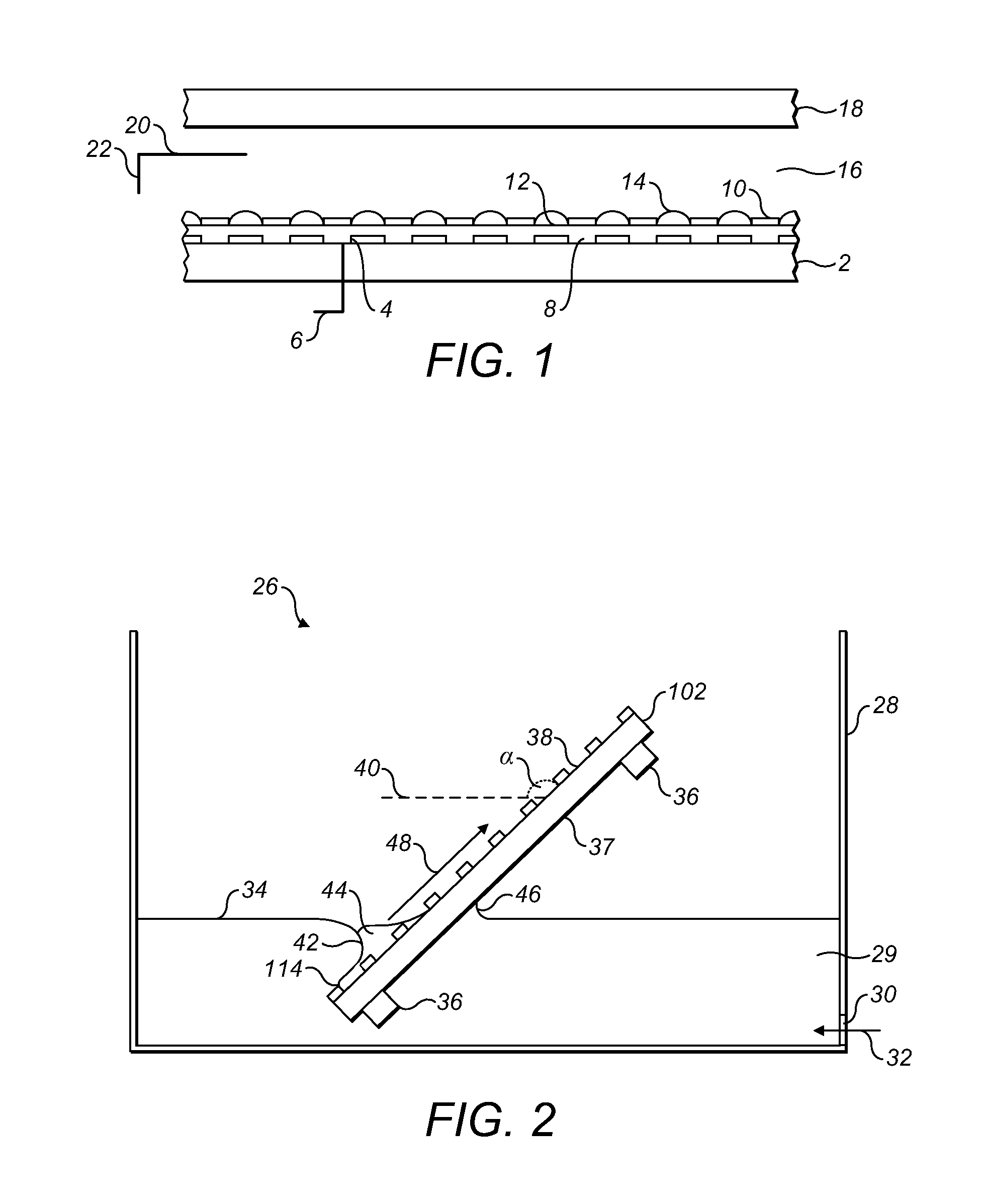
[0047]FIG. 1 shows a cross-section of a series of electrowetting elements made using the method according to the invention. A first substrate 2 is provided with electrodes 4, deposited as a thin-film conductor on the substrate. Each electrode is connected to a signal line 6 for providing a voltage. The electrodes are covered by a thin hydrophobic layer 8 of the amorphous fluoropolymer AF1600. A pattern of a thin hydrophilic layer 10 of SU8 divides the surface of the substrate in hydrophobic first areas 12 between the hydrophilic second areas 10. These first areas may be referred to as pixel areas. The size of the first areas is, for instance, 160 micrometres square, the second areas can have a width of 10 micrometres and a height of 3 to 6 micrometres. The first substrate 2, provided with the layers 4, 8 and 10, is subjected to the method according to the invention using oil as first fluid, water as second fluid and air as third fluid or another combination of fluids. After carrying...
PUM
 Abstract
Description
Claims
Application Information