Spray nozzle and the application

a spray nozzle and spray nozzle technology, applied in the field of spray nozzles, can solve problems such as interfering with each other, and achieve the effects of reducing the bounce back of fluid flow, reducing the waste of fluid flow, and avoiding any unexpected flow and/or spots

Inactive Publication Date: 2015-09-22
TAKAHARA HIROSHI
View PDF22 Cites 12 Cited by
  • Summary
  • Abstract
  • Description
  • Claims
  • Application Information

AI Technical Summary

Benefits of technology

[0012]Accordingly several advantages of this invention are as follows: to develop spray nozzles with internal and external designs that perform the fluid flow pattern and distribution fluidly and dynamically during interfering and changing the fluid flow and the particles' direction, and eliminate any unexpected flow and/or the spots.
[0013]It will reduce waste from fluid flow bounce back because the particles are under a lower pressure, which meets the environment requirement to save fluids used; such as paints for many external applications.
[0014]It will increase the efficiency with a bett

Problems solved by technology

Because the orifices are designed very close each other with an optimal flow angle, these t

Method used


Image

  • Spray nozzle and the application
  • Spray nozzle and the application
  • Spray nozzle and the application

Examples


Embodiment Construction

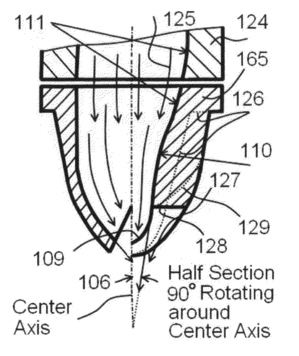
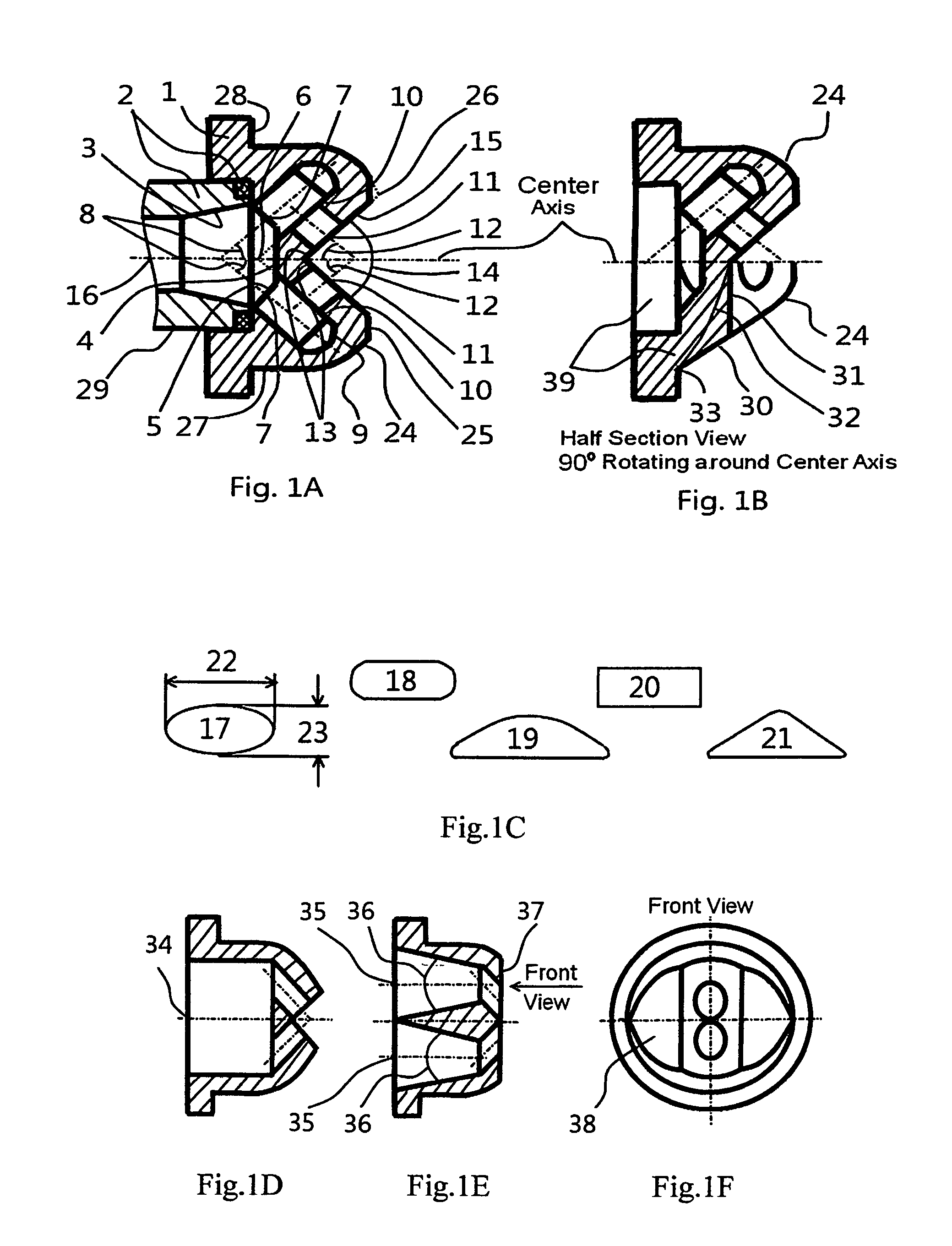
[0024]FIG. 1A, FIG. 1B and FIG. 1C show a spray nozzle design and the configuration. A spray nozzle 1 is assembled with a seal assembly 2, which is designed variously to meet the internal flow requirements of the nozzle 1 and the system to be applied with. The angle of taper 3 is defined between 0 degrees and 180 degrees and the surface is a concave surface or a convex surface to allow the fluid smoothly flow into the holes 7. The internal flow channel is designed with a flat surface 4 and a taper surface 5, or combined to one radius surface together, any other shape or intersected at point 6 to allow the fluid smoothly flow into holes 7. The holes 7 are manufactured with angle 8 between 15 degrees and 75 degrees. The holes 7 are tapered between 0 and 45 degrees. The surfaces 9 is a radius surface or other different shapes such as the taper, flat, etc. The distance 10 from the edge of the hole 11 is 0.1 at least times of hole size 11 to have a better fluid flow. The angle 12 of the ...


PUM


Abstract

A spray nozzle for providing a high efficient atomization and a uniform fluid flow pattern, includes an internal fluid channel, sealing and a spray nozzle, on which two of spray orifices are designed close to each other. The fluid flow is guided in the internal fluid channel smoothly and separated to two fluid flows inside of spray nozzle. These two fluid flows are pressed out from the spray orifices and interfered with each other right after flow out from the spray orifices. The fluid is being atomized efficiently because the spray nozzle is designed to fully utilize both flow velocity energy and flow pressure potential energy, which is well known as “Potential Core” or “Potential Zone” and will disappear in a very short distance right after fluids flow out from the spray orifices. During the fluid flows collide with each other by using the flow velocity right after flow out from the orifices, the fluid flows explode within the potential core by using the flow pressure potential energy. And then, the fluid flow and the fluid particles are continuously atomized by using the velocity difference between the fluid flow and the air around the fluid flow to have very fine particles.

Description

BACKGROUND OF THE INVENTION[0001]1. Field of the Invention[0002]This invention relates to a spray nozzle for high pressure, airless spraying of paint and other fluids, and more particularly, to a spray orifice design, which produces a uniform fluid flow pattern and high efficient atomization. The new spray nozzle is designed to fully utilize both flow velocity energy and flow pressure potential energy, which exists in the fluid flow near to spray orifices. It has a wide application in various industrial fields.[0003]2. Description of the Related Art[0004]The current airless spray nozzle requires a high fluid velocity at the nozzle outlet under a high pressure to obtain a high fluid atomization flow pattern. The spray nozzle outlet is designed to various shapes to meet the fluid flow pattern requirements as well. The fluid flow is adjusted and guided at inside of the nozzle before flowing out. Under a high pressure, the fluid is pressed out from the nozzle and atomized starting from ...

Claims


Application Information

Patent Timeline
IPC IPC(8): B05B1/26B05B1/02
CPCB05B1/02B05B1/048B05B1/26
Inventor TAKAHARA, HIROSHI
Owner TAKAHARA HIROSHI
Why Eureka
Try Eureka