
Optical communication devices having optical time domain reflectometers

a technology of optical time domain and optical communication device, which is applied in the direction of electromagnetic transmission, transmission monitoring, electromagnetic transceivers, etc., can solve the problems of ensuring adequate isolation between the difficulty of ensuring the isolation of the otdr signal and the data signal, and the interference of the optical data signal transmitted through the fiber

Active Publication Date: 2015-09-22
ADTRAN
View PDF8 Cites 27 Cited by
  • Summary
  • Abstract
  • Description
  • Claims
  • Application Information

AI Technical Summary

Benefits of technology

The patent text describes a communication device that includes an optical transceiver with an embedded optical time domain reflectometer (OTDR) for monitoring the health of optical fibers in fiber networks. The device is designed as a small form factor pluggable (SFP) and includes two optical transmitters and two optical receivers. The device operates simultaneously with data transmission and can isolate the OTDR signal from the data signal. The technical effect of this invention is to provide a reliable and efficient solution for monitoring the health of optical fibers in fiber networks while minimizing interruptions to data transmission.

Problems solved by technology

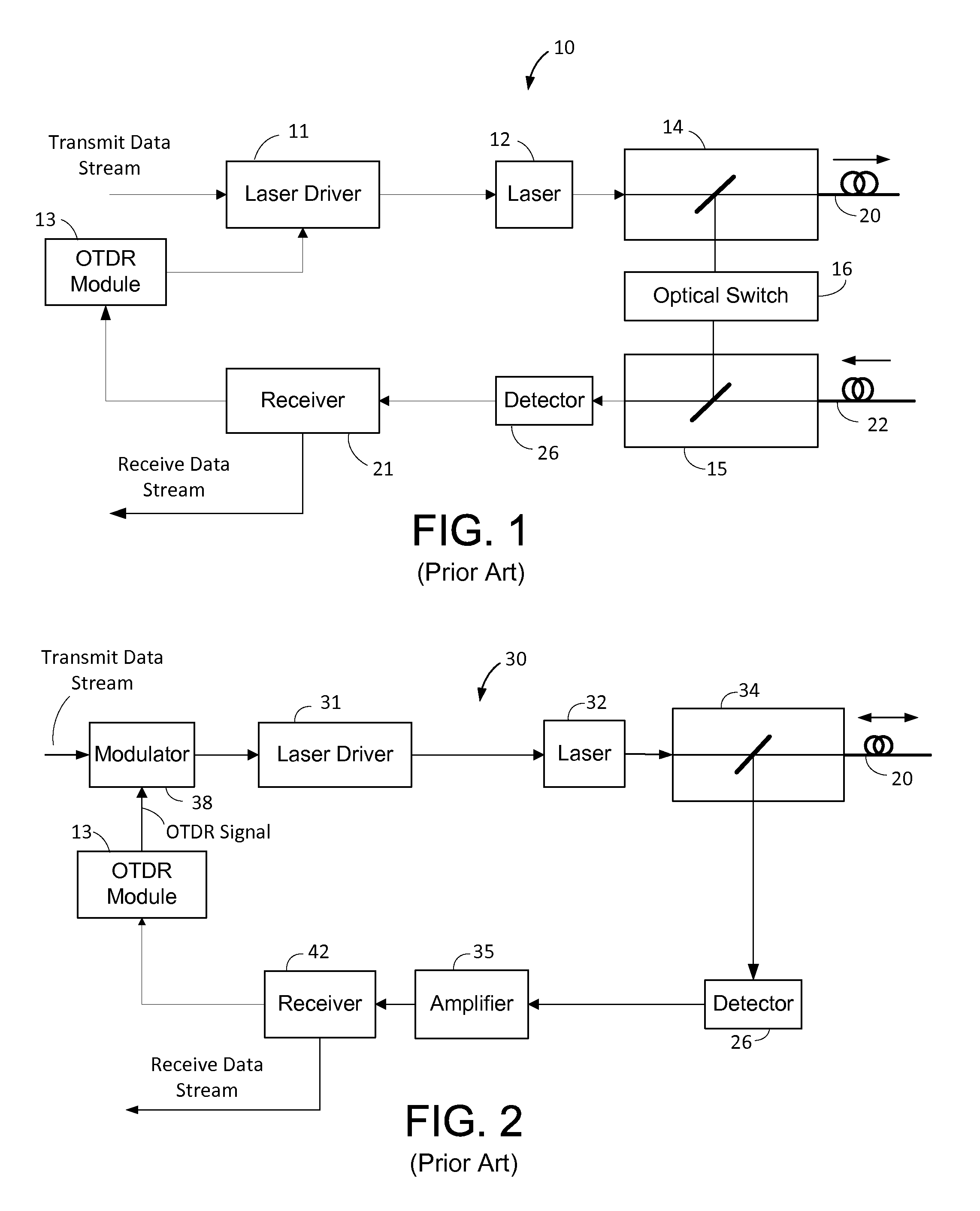
In many cases, the light used by an OTDR to probe an optical fiber for anomalies can interfere with the optical data signal transmitted through the fiber.
Since interrupting data transmission is undesirable, techniques have been developed to permit the OTDR to operate simultaneously with data transmission.
However, ensuring adequate isolation between the OTDR signal and the data signal can be problematic.
This isolation problem becomes particularly challenging as the size of the transmit and receive subsystems connected to the optical channel are reduced, limiting the size of certain components, such as directional couplers and filters, typically used to isolate data signals and OTDR signals.
Indeed, there exists a heretofore unaddressed need in the art for techniques and designs for embedding an OTDR in an SFP while achieving sufficient communication and testing performance, including, in particular, good isolation between the OTDR signal and the data signal.

Method used


Image

  • Optical communication devices having optical time domain reflectometers
  • Optical communication devices having optical time domain reflectometers
  • Optical communication devices having optical time domain reflectometers

Examples


Embodiment Construction

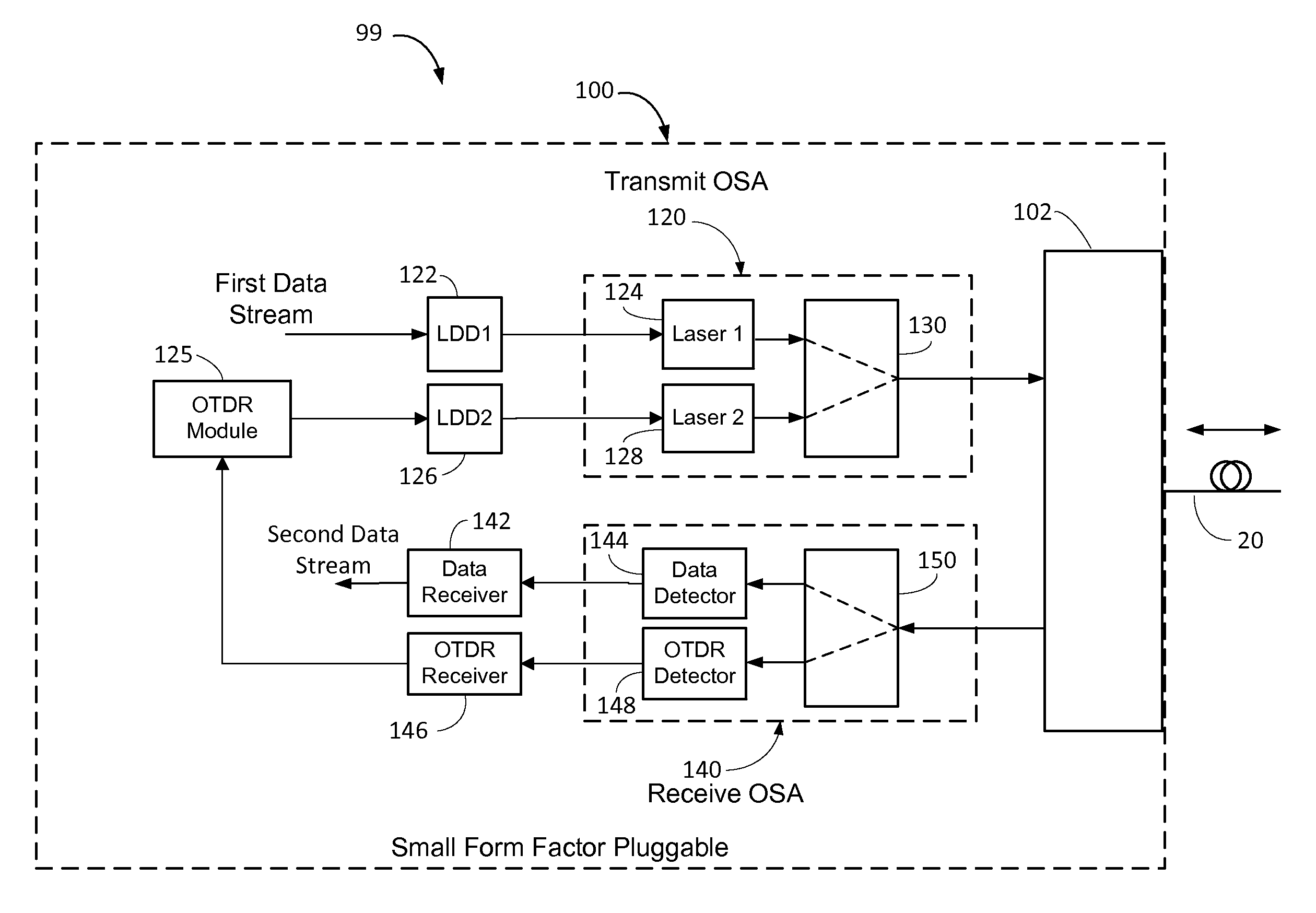
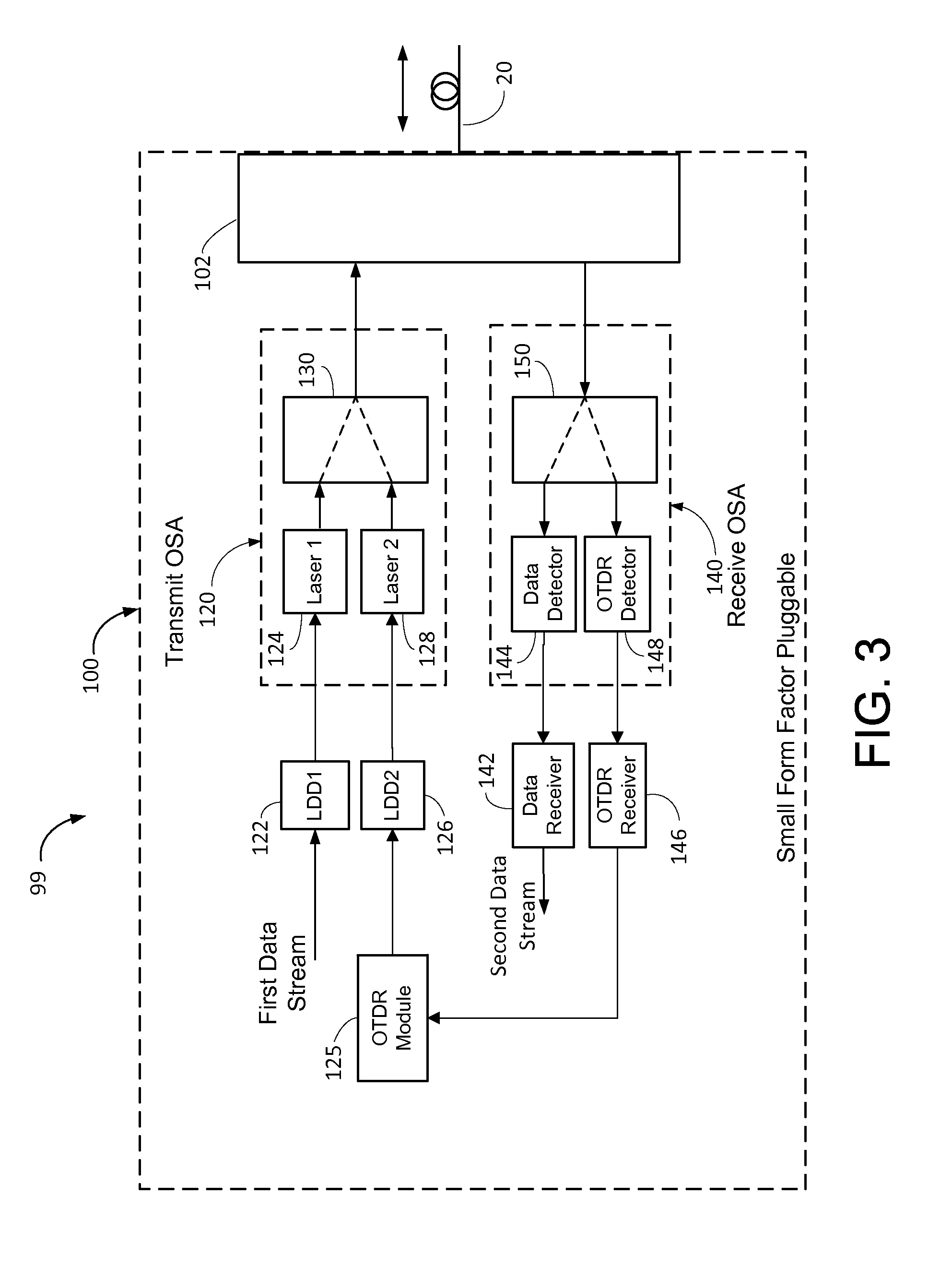
[0011]The present disclosure generally pertains to optical systems and methods for communicating data across an optical fiber while simultaneously probing the fiber for anomalies. In one exemplary embodiment, a communication device has an optical transceiver packaged as a small form factor pluggable (SFP) package and includes an embedded optical time domain reflectometer (OTDR). The SFP package has an optical subassembly (OSA) coupled to an optical fiber, and the OSA has two optical transmitters. One of the optical transmitters is configured to transmit a first data signal at a first wavelength through the optical fiber, and the other optical transmitter is configured to transmit an OTDR signal at a second wavelength through the optical fiber. The SFP package also has another OSA that is optically coupled to the optical fiber, and this other OSA has two optical receivers. One of the optical receivers is configured to receive a second data signal at a third wavelength from the optica...


PUM


Abstract

A small form factor pluggable (SFP) device has an embedded optical time domain reflectometer (OTDR) for detecting anomalies along an optical fiber. The SFP device has a plurality of optical subassemblies (OSAs) that are used to transmit an optical data signal at a first wavelength, transmit an optical OTDR signal at a second wavelength, and receive an optical data signal at a third wavelength. The OTDR signal is effectively isolated from the data signals based on wavelength, and samples of returns of the OTDR signal are analyzed to detect at least one anomaly along the optical fiber.

Description

CROSS REFERENCE TO RELATED APPLICATION[0001]This application claims priority to U.S. Patent Application No. 61 / 607,372 entitled “Optical Networks Having Optical Time Domain Reflectometers Embedded in Small Form Factor Pluggables” and filed on Mar. 6, 2012, which is incorporated herein by reference.RELATED ART[0002]Small form factor pluggable (SFP) devices are often used as components of fiber networks as they often help to save space and reduce cost. Such SFP devices are typically coupled to electrical devices and used to convert signals between the electrical domain and the optical domain. As an example, an SFP device might convert an electrical signal to an optical signal by modulating a laser with data defined by the electrical signal. Such an optical signal may then be communicated through a passive optical network (PON) or other type of optical system. PONs often have relatively high data bandwidths making them attractive for use as a data transport backbone of a communication ...

Claims


Application Information

Patent Timeline
Patent Type & Authority Patents(United States)
IPC IPC(8): H04B10/071H04B10/40H04B10/25
CPCH04B10/071H04B10/2503H04B10/40H04Q11/0067H04Q2011/0083H04B10/2589
Inventor SANDSTROM, LEIF J.
Owner ADTRAN
Learn More