Refrigerated display cabinet

a display cabinet and refrigerator technology, applied in the field of refrigerated display cabinets, can solve the problems of significant volume of cooled air to be lost into the surrounding environment, high energy consumption and thus operating costs, and the loss of cooled air in the refrigerated display cabinet having front or rear surfaces with doors in them

Inactive Publication Date: 2015-09-29
BRYCE ALASDAIR JAMES
View PDF7 Cites 4 Cited by
  • Summary
  • Abstract
  • Description
  • Claims
  • Application Information

AI Technical Summary

Benefits of technology

[0014]In this way, when the at least one door is opened, refrigerated air which is deflected to flow in the secondary flow path is not lost to the surrounding environment. This provides an enhanced cooling effect of the air in the lower part of the chamber so that, when the at least one door is re-closed and the primary flow path re-established, the air in a remaining part of the chamber is quickly re-cooled to a desired level. This is in spite of the fact that refrigerated air is lost from the remaining part of the chamber into the surrounding environment (and warmer ambient air enters the remaining part of the chamber) during the period when the door is open. The retention of refrigerated air in the lower part of the chamber, and the quick re-cooling of the air in the remaining chamber part, help to reduce energy usage and thus operating costs of the cabinet. It also helps to maintain food or drink items in the chamber at a sufficiently low temperature.
[0017]The cabinet may be arranged such that, when the at least one door is opened, the flow channel is substantially entirely or entirely obstructed, such that the flow of air towards the top of the chamber is substantially entirely or entirely prevented. This facilitates the recirculation of refrigerated air in the lower part of the chamber during the period when the at least one further door is open. In this condition, the air circuit is of a reduced size resulting in a more concentrated chilling effect. The at least one door may be the at least one further door.
[0021]The lower and at least one further door may be arranged such that only one door may be opened at any one time. This may be achieved by arranging the door which is open to block or restrict said other door from being opened. Alternatively it may be achieved by arranging a restraining member to restrict opening of one of the doors when the other is open. When the lower door is open the at least one further door may be restricted from being opened as will be shown in FIG. 8 where door 30 is blocked by door 24. This may promote the flow of air along a portion of the flow channel defined between the further door and the shelf and restrict loss of cooled air from the further part of the chamber. When the at least one further door is open the lower door may be restricted from being opened as will be shown in FIG. 9 where door 24 is blocked by door 30. This may promote the flow of air in the secondary flow path and restrict loss of cooled air from the lower part of the chamber.
[0023]The lower door and the at least one further door may each extend across the full width of the opening. The lower door and the at least one further door may each extend only part way across the opening in the height direction of the opening. The lower door may extend from a lower edge of the opening towards a top edge of the opening, and may only extend part of the way towards the upper edge. The at least one further door may extend from the lower door towards the upper edge of the opening, and may extend from the lower door to the upper edge of the opening. This may provide the advantage that, when the lower door is opened (and the at least one further door closed), a flow of refrigerated air along the flow channel is maintained. This is because only part of the chamber is open to the environment, along the height of the opening. This is in contrast to prior cabinets, where doors extend the full height of the opening and so refrigerated air is easily lost into the surrounding environment, and indeed warmer ambient air may more easily enter the chamber.
[0025]The further door may be arranged so that it rests upon a top edge of the lower door when it is opened. The lower door may thereby support the further door when it is in the open position.
[0030]The at least one shelf may be arranged so that, when the at least one further door is opened, air is deflected to flow from the flow channel along a lower surface of the shelf and around the lower part of the chamber. The at least one shelf may be positioned relative to the lower and at least one further door so that, when the at least one further door is opened, at least part of said door lies substantially parallel to the lower surface of the shelf and extends into the chamber aligning with the front or rear of the shelf. This promotes the flow of air around the lower part of the chamber; the shelf acts as a baffle to direct the flow of air. Where an additional door is provided, a shelf may be similarly located in relation to the additional door.

Problems solved by technology

Refrigerated display cabinets having front or rear surfaces with doors in them suffer from a particular problem of loss of cooled air.
It has been found that opening a door in a cabinet can cause a significant volume of cooled air to be lost into the surrounding environment, and warmer ambient air to enter.
Firstly, when cooled air is lost through the open door, the circulation of cooled air within the chamber is disrupted, with the result that the temperature in the chamber is higher than desired during the time when the door is open. As a consequence, when the door is closed, the refrigeration system has to perform additional work in order to re-cool the air in the chamber to the required level. This leads to high energy usage and thus operating costs.
Secondly, the loss of cooled air into the surrounding environment, and the entry of warmer ambient air, also leads to an increase in the temperature of the air in the chamber. This is a particular problem as the cabinets are frequently used in areas where the ambient air temperature is relatively high. As a result, the temperature of the food or drink items in the cabinet may not be maintained at a sufficiently low level. This can lead to the food or drink items becoming too warm, with the result that they may at least be unpalatable, but that they may also present a danger to health, or may require to be disposed of earlier than would otherwise be the case.
Thirdly, the refrigeration system may include a compressor, which is an expensive component. The compressor functions to compress a coolant which, when it subsequently expands, creates a cooling effect which is utilised to cool the air flowing into the display chamber. The loss of cooled air into the surrounding environment, and the entry of warmer ambient air into the display chamber, results in the compressor having to do additional work to maintain the air in the chamber at the required temperature level. This puts additional strain on the compressor, and reduces its effective life so that it requires more regular maintenance than might otherwise be the case, and possibly early replacement.
These problems are exacerbated in high usage environments, where the doors are frequently being opened and closed.
In both cases, the result of this is that air is lost from the chamber when the door(s) are opened, as the chamber is open to the surrounding environment over its entire height.

Method used


Image

  • Refrigerated display cabinet
  • Refrigerated display cabinet
  • Refrigerated display cabinet

Examples


Embodiment Construction

[0043]Embodiments of the present invention will now be described, by way of example only, with reference to the foregoing drawings. The foregoing drawings are not intended to define a cabinet which has specifically front or rear facing doors and it is assumed that the cabinet and thus the doors can face in either direction.

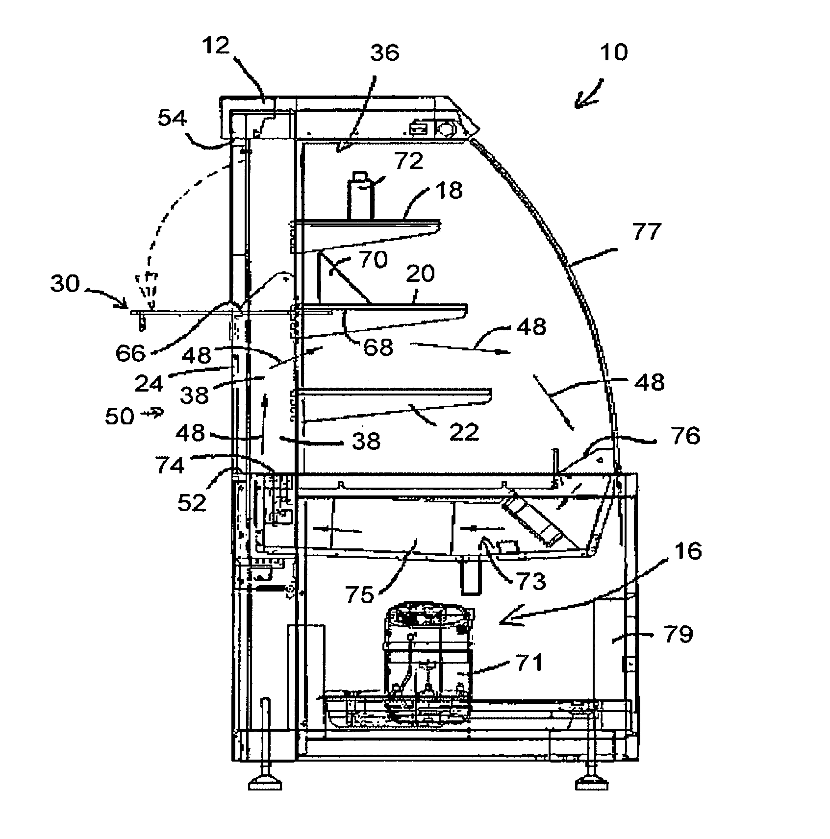
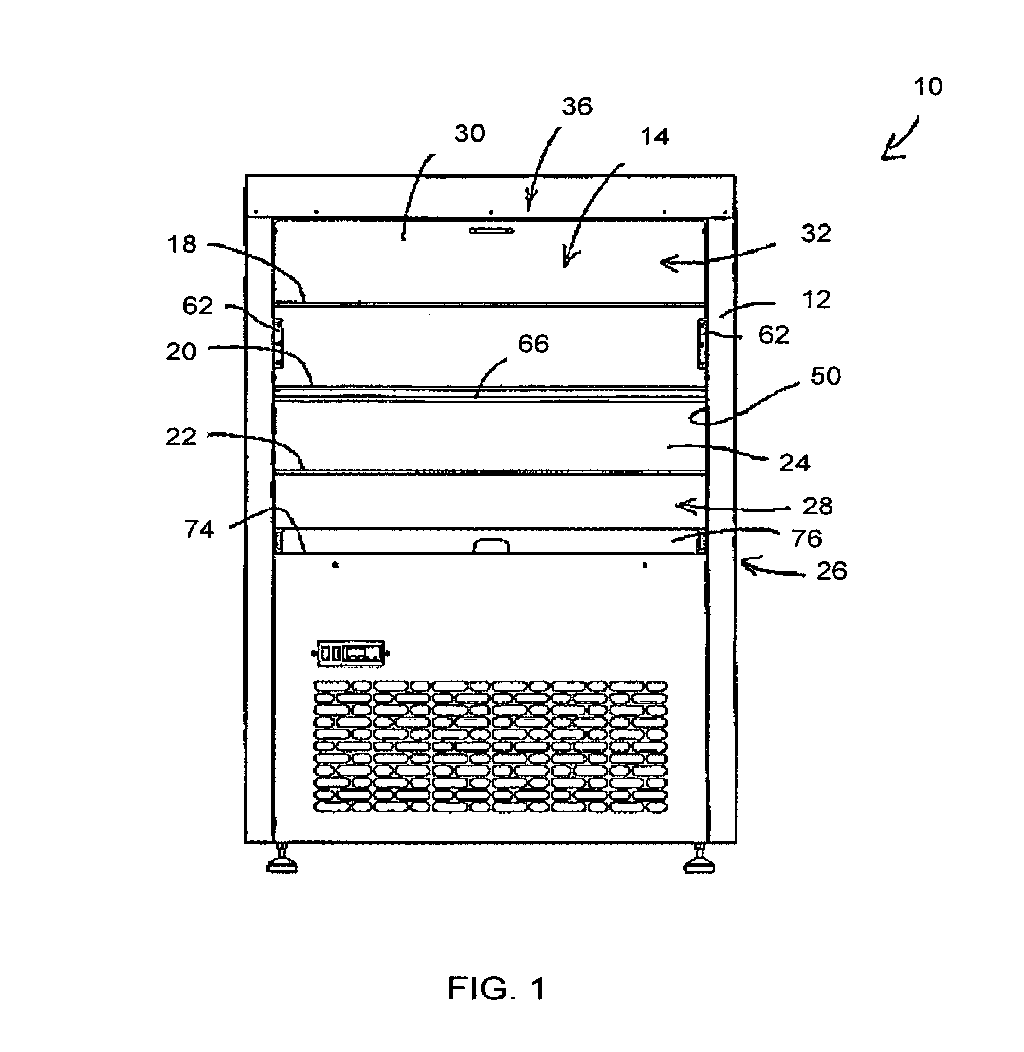
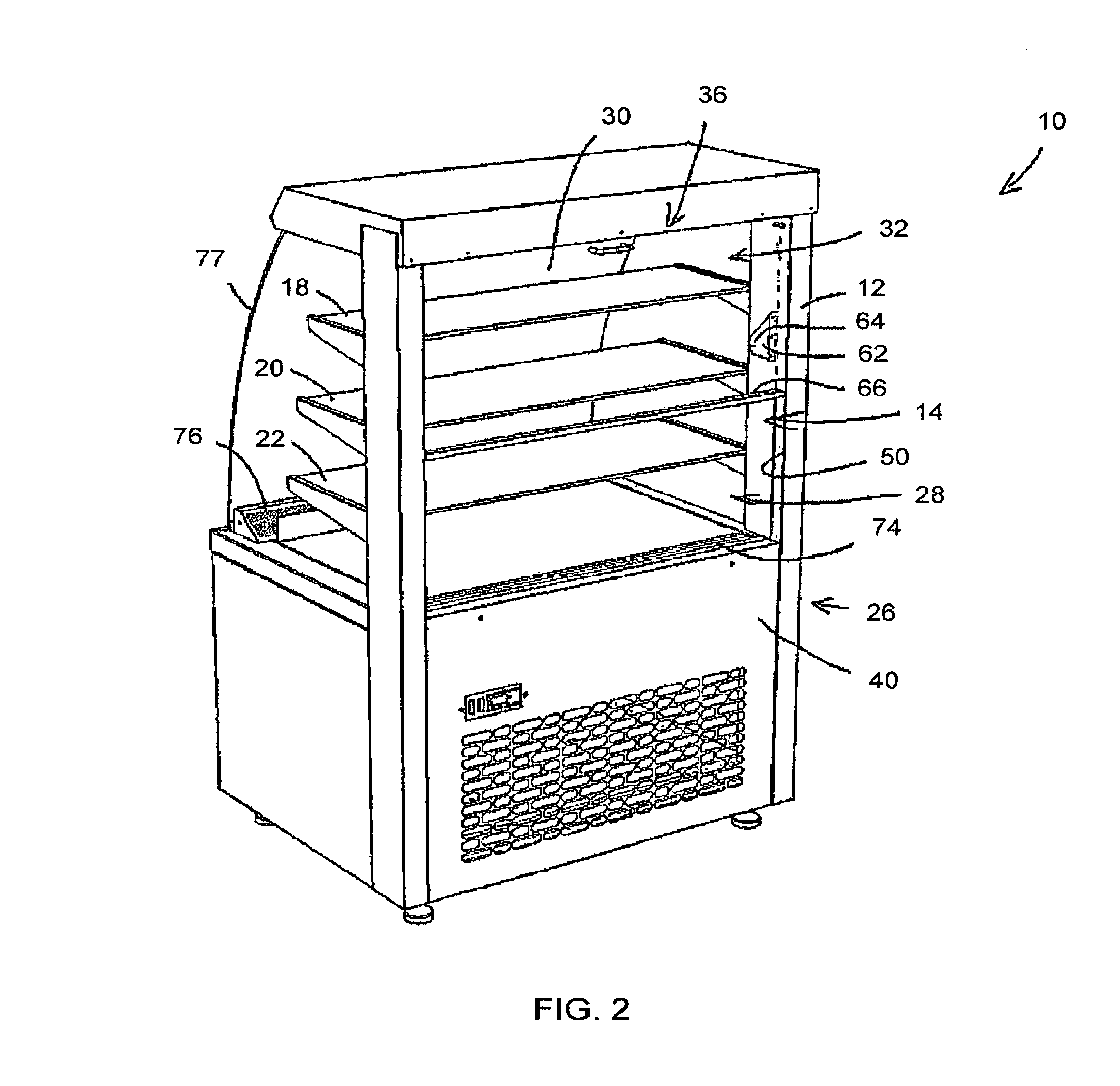
[0044]Turning firstly to FIGS. 1 and 2, there are shown elevation and perspective views, respectively, of a refrigerated display cabinet in accordance with an embodiment of the present invention, the cabinet indicated generally by reference numeral 10. The cabinet 10 is also shown in FIGS. 3, 4 and 5 which are schematic side views showing the cabinet in use.

[0045]The cabinet 10 generally comprises a housing 12 which defines a display chamber 14. The cabinet 10 also comprises a refrigeration system 16 (FIGS. 3 to 5), for circulating refrigerated air around the chamber 14. At least one shelf is mounted in the chamber 14, for receiving items to be displayed and, in t...


PUM


Abstract

A refrigerated display cabinet having novel door and shelf system configured to minimize any rise in cabinet temperature during door opening. The door and shelf system can have the effect of deflecting refrigerated air into an alternative circulation pattern when doors are open. In this way, cabinet efficiencies are maintained during the time in which the doors are opened.

Description

CROSS-REFERENCE TO OTHER RELATED APPLICATIONS[0001]This application relates to and claims priority from GB Patent Application Number GB 1112450.0, filed on Jul. 20, 2011, disclosure of which is incorporated herein by reference.BACKGROUND OF THE INVENTION[0002]1. Field of the Invention[0003]The present invention relates to a refrigerated display cabinet. In particular, but not exclusively, the present invention relates to a refrigerated display cabinet having a housing defining a display chamber, at least one shelf mounted in the chamber for receiving items to be displayed, and a refrigeration system for circulating refrigerated air around the chamber. Refrigerated display cabinets are utilised in retail, catering and convenience establishments for storing chilled food or drinks, and for displaying the food or drink items in an attractive manner.[0004]A wide range of different types of cabinets have been produced, to suit the needs of the various different establishments which utilis...

Claims


Application Information

Patent Timeline
Patent Type & Authority Patents(United States)
IPC IPC(8): A47F3/04A47F10/06
CPCA47F3/0408A47F10/06
Inventor BRYCE, ALASDAIR JAMES
Owner BRYCE ALASDAIR JAMES
Why Eureka
Try Eureka