Tube and pipe benders and methods of bending same

a technology of bending tubes and forming bars, which is applied in the direction of shaping tools, forging/pressing/hammering apparatuses, forging/hammering/pressing machines, etc., can solve the problems of time-consuming and cumbersome procedure for switching out forming bars, loss of other forming bars, and difficulty in finding other forming bars, etc., to achieve the effect of reducing friction

Active Publication Date: 2015-09-29
DIVERSITECH
View PDF24 Cites 12 Cited by
  • Summary
  • Abstract
  • Description
  • Claims
  • Application Information

AI Technical Summary

Benefits of technology

[0017]One advantage of the invention is that a user may utilize different-sized forming mandrels for different size tubing without needing to install separate forming bars or disassembling the forming bar. If a particularly-sized forming mandrel is not located on the side of the forming bar presently installed, the user may merely remove and flip forming bar over to use the forming mandrels located on the other side. In embodiments where the bender has a quick connect-disconnect mechanism, this may be accomplished without the need for tools or removing cumbersome screws, bolts or nuts. Another advantage of the invention is that the relief surfaces of the bending mandrel reduce friction and help prevent the tube from become jammed or difficult to remove from the mandrel after bending.

Problems solved by technology

However, the inventors have discerned a number of disadvantages of previously known crossbow benders.
One disadvantage is that such benders are difficult to set-up and operate.
This procedure to switch out forming bars can be time-consuming and cumbersome.
In addition, as only one of the forming bars is attached to the bender, the other forming bar(s) may become lost or difficult to find in a toolbox, which may be full of different tools.
Further, it may be unclear or not easy to identify which forming bar is to be utilized with particular tubing.
Thus, the Rothenberger device still requires time-consuming and cumbersome rearrangement of the mechanism.
Another problem identified in previous crossbow benders is that, after bending, the tube can be difficult to remove from the bending mandrel.
Not only does removing a tube that is “stuck” in the bending mandrel take time and effort, but the force required to remove or unstick the bent tube can damage or distort the tube, or alter the bend or shape of the tube, which is undesirable.

Method used


Image

  • Tube and pipe benders and methods of bending same
  • Tube and pipe benders and methods of bending same
  • Tube and pipe benders and methods of bending same

Examples


Embodiment Construction

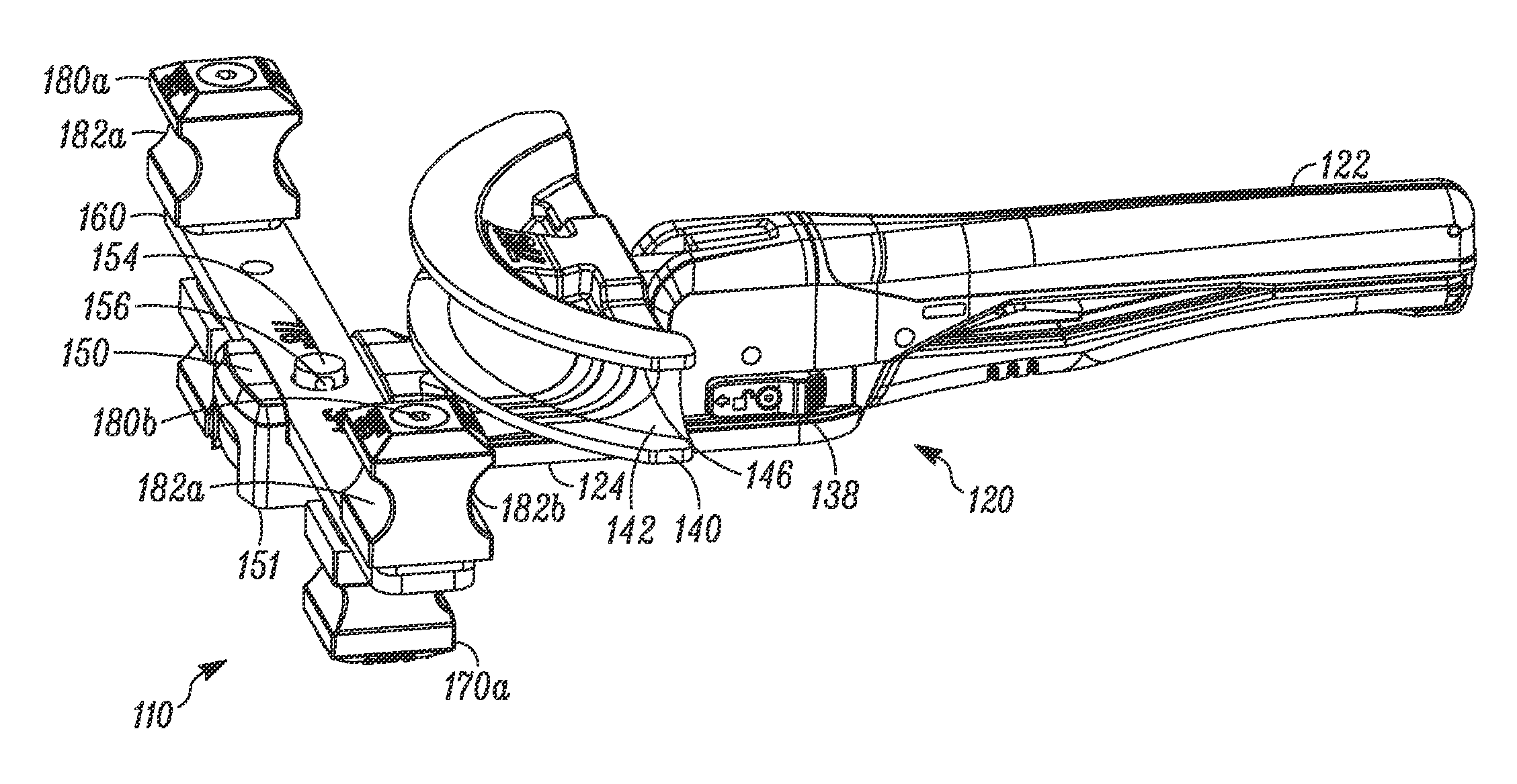
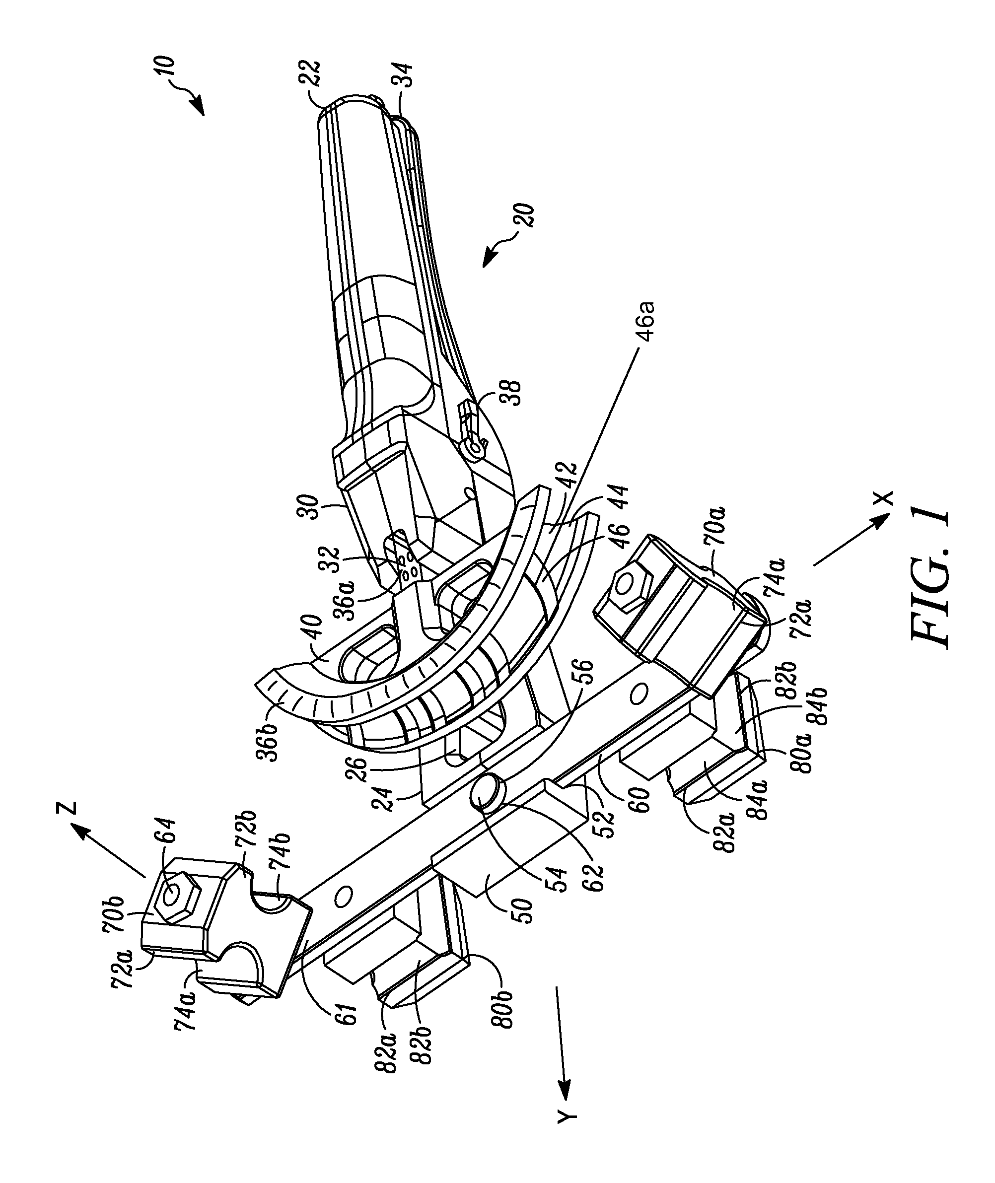
[0026]In FIG. 1, a tubing bender indicated generally by the reference numeral 10 has a base portion 20 and a cross bar or forming bar 60. The words “tubing” or “tube” as used herein should be understood to mean tubing, such as, for example, copper, aluminum, steel, stainless steel, or other metal tubing, or tubing made with a non-metallic material, piping being made out of any material, a rod material, or any other workpiece onto which it is desired to impart a bend or curve. Further, these terms should be understood to refer to work pieces having any shape or cross-section, e.g., round, oval, rectangular, square, solid, etc.

[0027]The base portion 20 has a handle portion 22 at one end generally shaped to be held by a user to hold the bender 10, and a holding portion 50 at an end opposite the handle portion. Between the handle portion 22 and holding portion 50 is a guide portion 24. As seen in FIG. 1, the guide portion 24 has a cavity 26. The cavity reduces the amount of material of ...


PUM

PropertyMeasurementUnit
specific diameteraaaaaaaaaa
sizesaaaaaaaaaa
diameteraaaaaaaaaa

Abstract

In a crossbow-style tube bender, a curved bending mandrel having a channel into which the tube in bent to form the bent tubing length has at least one relief surface forming a localized recess or depression in the surface of the channel. A forming bar or cross bar adapted to cooperate with a bending mandrel has on a first side of the forming bar a least one first pair of forming mandrels configured for a first tubing size, and on a second side of the forming bar has at least one second pair of forming mandrels configured for a second tubing size. The bender has a quick connect-disconnect mechanism permitting quick disconnection from and connection to the forming bar to utilize either the at least one first or at least one second pairs of forming mandrels.

Description

CROSS-REFERENCE TO RELATED APPLICATIONS[0001]The patent application claims benefit under 35 U.S.C. §119(e) to U.S. provisional application Ser. No. 61 / 454,891, filed Mar. 21, 2011, titled “Tube and Pipe Benders and Methods of Bending Same”, which is hereby expressly incorporated by reference as part of the present disclosure.FIELD OF THE INVENTION[0002]The present invention relates to tube benders, and more particularly, relates to “crossbow-style” benders.BACKGROUND INFORMATION[0003]Crossbow-style benders are used to bend tubing or piping for a variety of applications. Crossbow benders are helpful in achieving the desired bend angle with accuracy. However, the inventors have discerned a number of disadvantages of previously known crossbow benders.[0004]One disadvantage is that such benders are difficult to set-up and operate. To accommodate different tubing or piping sizes, shapes and bend radii, the forming bar, which acts against the side of the tubing opposite the mandrel, must ...

Claims


Application Information

Patent Timeline
Patent Type & Authority Patents(United States)
IPC IPC(8): B21D7/06
CPCB21D7/063Y10T29/49716
Inventor HOULE, JOSEPH J.WORTELBOER, DAVID
Owner DIVERSITECH
Why Eureka
Try Eureka