
Optical acoustic panel

a technology of optical acoustic panels and acoustic panels, which is applied in the direction of lighting elements, lighting and heating apparatuses, instruments, etc., to achieve the effects of preventing too much glare, facilitating efficient manufacturing, and facilitating the manufacture of acoustic panels

Inactive Publication Date: 2015-09-29
KONINKLIJKE PHILIPS ELECTRONICS NV
View PDF12 Cites 22 Cited by
  • Summary
  • Abstract
  • Description
  • Claims
  • Application Information

AI Technical Summary

Benefits of technology

[0024]Optionally, the thickness of the walls is smaller than ⅕ of the pitch of the raster structure. This results in a higher efficiency and a better skylight appearance. In another option, the thickness of the walls is smaller than 1 / 10 of the pitch of the raster structure, which results in even better advantageous effects.
[0025]Optionally the optical spacing structure comprises a stretched-out stack of elongated layers. Pairs of successive layers are joined together at a plurality of points. Successive pairs of successive layers are joined together at different points. The layers form the walls of light transmitting channels. The light transmitting channels are formed by spaces between two successive layers of the stretched-out stack of elongated layers. The point-wise joining of layers may be carried out by gluing. Such a spacing structure may be manufactured very efficiently. Elongated stripes of a blue material are successively glued together such that the glue-points of successive pairs of successive layers are different in a direction following the elongated layer, and after the gluing, the stack of elongated layers is stretched-out to obtain the spacing structure. Further, besides the fact that such a structure may be manufactured efficiently, the optional features may result in further benefits in the distribution and storages of the spacing structure. Namely, it is not necessary to stretch out the stack of layers immediately after gluing the layers together. This may also be performed just before the micro perforated foil is arranged to the first side of the spacing structure. Thus, after gluing the layers together, the stack may be stored or distributed in its most compact shape.
[0026]Optionally, a surface of the walls facing towards the light transmitting channel is diffusely reflective in the predefined spectral range. Such a wall reflects the light which impinges on the wall back towards the light transmitting channel, and because the wall is blue, blue light is reflected back. Most of this reflected light will exit the light transmitting channel via the light exit window, either directly or after one or more additional reflections. Furthermore, a diffusely reflective side of the wall results in an advantageous spreading of light emission angles of the bluish light. Walls having this characteristic may be manufactured of a large set of materials. Just two possible examples are: a plastic with a blue dye, or a metal on which a blue reflective or blue diffusely reflective coating is applied.
[0027]Optionally, the walls are light transmitting in the predefined spectral range. If light impinges on the walls and is transmitted through the (blue) walls, the light output of the optical element at relatively large light emitting angels comprises light that passed the light transmitting walls and is consequently more blue (more saturated blue). As such it contributes to the daylight appearance. Several materials may be used, like blue transparent synthetic materials. If a plurality of light transmitting cells is arranged in a raster structure, and if a user views towards the optical acoustic panel comprising the spacing structure with blue light transmitting walls, the bluish light becomes more (saturated) blue at larger viewing angles. Light impinges on the walls at relatively large light emission angles with respect to a normal axis of the light input window, and is transmitted more than once through several blue light transmitting walls of successive light transmitting cells and as such the blue color is intensified at every passage of such a wall. This effect is experienced by user as a pleasant daylight appearance of the optical acoustic panel.
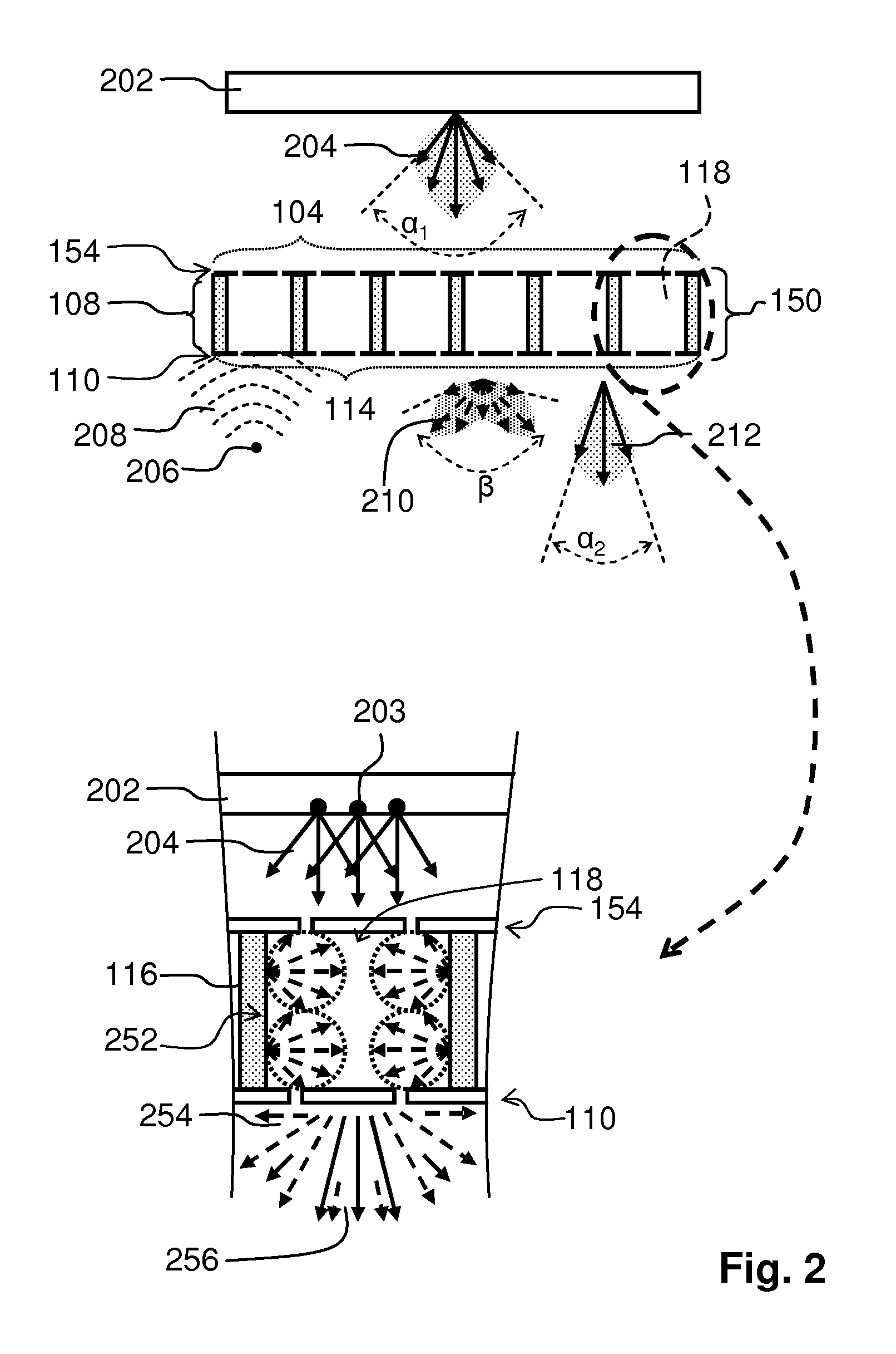
[0028]Optionally, a ratio between a diameter of the light transmitting channel and a length of the light transmitting channel is smaller than 3.4. The diameter of the light transmitting channel is defined as an average of the length of all possible imaginary straight lines through a centre point of the light transmitting channel from a point at the wall to another point at the wall along an imaginary plane parallel to the light input window. The length of the light transmitting channel is defined as an average of distances between the light input window and the light exit window measured along lines being parallel to the wall. To prevent too much glare, not too much light should be emitted at light emission angles which are larger than 60 degrees (for example, less than 1000 nits or candela per square meter). If the ratio is larger than 3.4, the light which is emitted at the center of the light exit window of the light transmitting cells has a cut-off angle at 60 degrees. The cut-off angle gradually increases towards 74 degrees at the border of the light exit window. Hence, glare is prevented. It is to be noted that the light emission at relatively large light emission angles also depends on the characteristics of the light that is received at the second side of the optical acoustic panel. If the received light comprises only a minor amount of light at relatively large light emission angles, not much light falls on the walls. If the received light comprises a substantial amount of its energy at relatively large light emission angles, the walls will reflect, in relative terms, much more light. For completeness, it is to be noted that still blue light is emitted at light emission angles larger than 60 degrees—however, the blue light is less glary light.
[0029]According to a second aspect of the invention a luminaire is provided which comprises the optical acoustic panel according to the first aspect of the invention. The optical acoustic panel is coupled to the luminaire and the second side of the optical acoustic panel is facing the luminaire. A surface of the luminaire closes the cavity. The luminaire according to the second aspect of the invention provides the same benefits as the optical acoustic panel according to the first aspect of the invention and has similar embodiments with similar effects as the corresponding embodiments of the optical acoustic panel.

Problems solved by technology

Especially when the space in which the optical acoustic panel is provided does not contain windows through which daylight is received, the well-being of people who are frequently in the space is not positively influenced by the lighting conditions in the space.

Method used


Image

  • Optical acoustic panel
  • Optical acoustic panel
  • Optical acoustic panel

Examples


Embodiment Construction

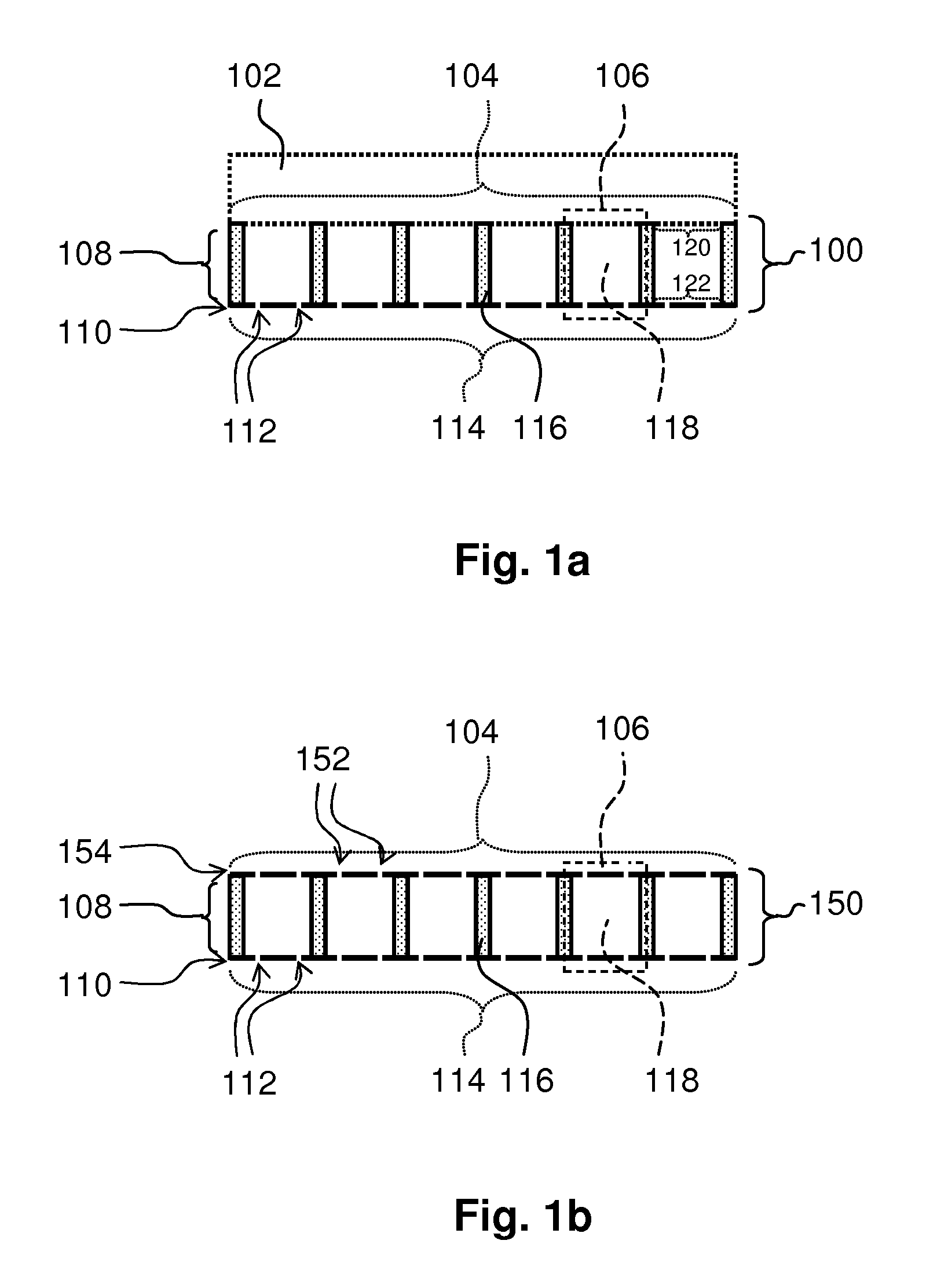
[0049]A first embodiment is shown in FIG. 1a. FIG. 1a schematically shows a cross-section of an embodiment of the optical acoustic panel 100 according to the first aspect of the invention. The optical acoustic panel 100 comprises a spacing structure 108 and a first micro perforated foil 110. The optical acoustic panel 100 has the first micro perforated foil 110 arranged at a first side 114 of the optical acoustic panel 100.

[0050]At a second side 104, being opposite the first side and being arranged parallel to the first side, the optical acoustic panel 100 is configured to be coupled to a means 102 which comprises a surface for closing a cavity between the first side and the surface. The means 102 is drawn schematically and may be a light source, a luminaire, or a transparent plate. A specific surface of the means 102 close the cavity, for example, the surface which is directly applied to the second side 104 of the optical acoustic panel 100, but, if the means does not have a surfac...


PUM


Abstract

An optical acoustic panel 100 for absorbing sound and providing a daylight appearance and a luminaire are provided. The optical acoustic panel 100 comprises a first side 114, a second side 104, a micro perforated foil 110 and a spacing structure 108. The first side 114 receives sound. The second side 104 is opposite the first side 114 and receives light. The micro perforated foil 110 comprises sub-millimeter holes 112, is light transmitting and is arranged at the first side 114. The sub-millimeter holes 112 are entrance holes of a cavity. The spacing structure 108 spaces the first side 114 at a predefined distance from the second side 104. The spacing structure 108 comprises a plurality of light transmitting cells 106. The light transmitting cells 106 comprise a light transmitting channel 118, a light exit window 122, a light input window 120 and a wall 116. The light transmitting channel 118 collimates a part of the light received at the second side 104 of the optical acoustic panel 100. The light transmitting channels 118 extend from the first side 114 towards the second side 104 and are filled with air. The light input window 120 is arranged at the second side 104. At least a part of the light exit window 122 being arranged at the first side 114. The wall 116 is interposed between the light input window 120 and the part of the light exit window 122. The wall 116 encloses the light transmitting channel 118. At least a part of the wall 116 being reflective or transmissive in a predefined spectral range for obtaining a blue light emission at relatively large light emission angles with respect to a normal to the first side 114.

Description

CROSS-REFERENCE TO PRIOR APPLICATIONS[0001]This application is the U.S. National Phase application under 35 U.S.C. §371 of International Application No. PCT / IB2012 / 055096, filed on Sep. 25, 2012, which claims the benefit of U.S. Provisional Patent Application No. 61 / 549,299, filed on Oct. 20, 2011. These applications are hereby incorporated by reference herein.FIELD OF THE INVENTION[0002]The invention relates to the field of optical acoustic panels.BACKGROUND OF THE INVENTION[0003]Micro perforated foils are used in specific acoustic panels. The acoustic panels provide a sound absorbing effect based on Helmholtz resonant sound absorption when the micro perforated foils are used in combination with a space behind the micro perforated foil. Such acoustic panels are, for example, discussed in “Micro-Perforated Structures as Sound Absorbers—A review and Outlook”, by Helmut V. Fuchs, Xueqin Zha, published in Acta Acustica united with Acustica, Volume 92, No 1, January 2006, pp 13-146. The...

Claims


Application Information

Patent Timeline
Patent Type & Authority Patents(United States)
IPC IPC(8): E04B1/84G10K11/172G10K11/16F21V33/00E04B1/86F21V11/14E04B1/74
CPCG10K11/16F21V33/006G10K11/172E04B1/8409E04B1/86E04B2001/748F21V11/14
Inventor SWINKELS, STEFAN HENRICUSVISSENBERG, MICHEL CORNELIS JOSEPHUS MARIE
Owner KONINKLIJKE PHILIPS ELECTRONICS NV
Learn More