
Inflatable floatable unit

a floatable unit and inflatable technology, applied in life-saving, vessel safety, rafts, etc., can solve the problems of occupying a lot of space, accumulating passengers, and occupying space for evacuation systems

Active Publication Date: 2015-10-06
VIKING LIFE SAVING EQUIP
View PDF7 Cites 5 Cited by
  • Summary
  • Abstract
  • Description
  • Claims
  • Application Information

AI Technical Summary

Benefits of technology

The present invention provides an improved evacuation system for passengers on a ship or similar vessel. The system includes an inflatable floatable unit with a flotation layer, a structural layer, and a flooring element. The structural layer has inflatable seating elements and a gangway for easy access. The invention allows for safe, fast, and intuitive evacuation of passengers and aids in organizing them.

Problems solved by technology

In passenger ships, the evacuation systems are designed for a large number of passengers and occupy a great amount of space on board.
Generally speaking, evacuation systems occupy space that could be utilised for passengers.
Present evacuation systems often utilise a combination of rescue boats or tender boats and inflatable life rafts arranged around the ship, occupying a lot of space.
As many passengers, especially on board cruise ships, demand an external cabin with a view, a problem has arisen with evacuation system primarily mounted on the outside of the ship as these often block the view.
The evacuation process will always be subject to bottlenecks and the resulting accumulation of passengers at certain positions.
Further, the organisation and positioning of passengers in the rafts have become an important issue with the growing raft size.
However, a large number of passengers seated in an unstructured manner may occupy much more space than intended.

Method used


Image

  • Inflatable floatable unit
  • Inflatable floatable unit
  • Inflatable floatable unit

Examples


Embodiment Construction

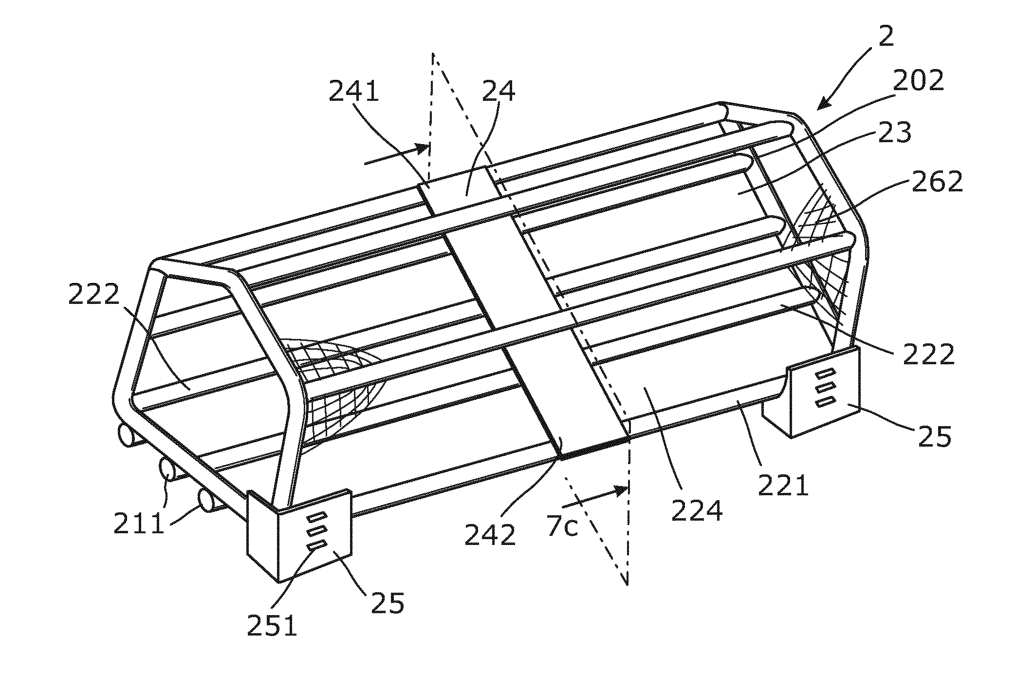
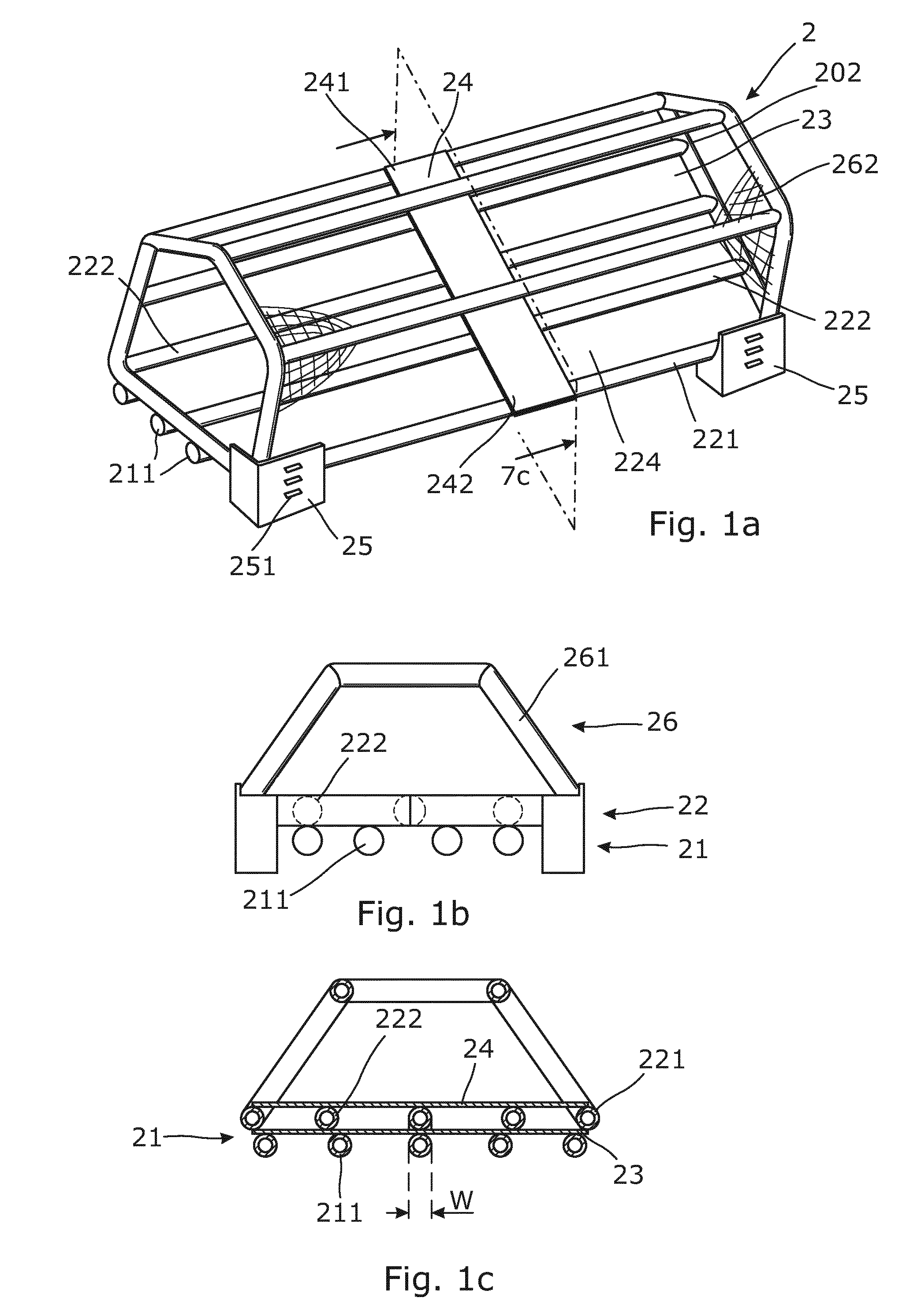
[0070]FIG. 1 shows an inflatable floatable unit 2 in an inflated condition. The inflatable floatable unit 2 comprises an inflatable flotation layer 21 arranged towards the lower part of the inflatable floatable unit when the inflatable floatable unit is regarded in a substantially upright position, as shown in FIG. 1a. The inflatable flotation layer 21 comprises a plurality of inflatable flotation tubes 211 extending along the inflatable floatable unit. The inflatable flotation layer 21 substantially provides the buoyancy keeping the inflatable floatable unit floating in the desired position.

[0071]Above the inflatable floatation layer, an inflatable structural layer 22 is provided. The inflatable structural layer comprises an inflatable outer tube 221 defining a circumferential barrier. The circumferential barrier in turn defines a protected area 224 enclosed by the inflatable outer tube element. A bottom part of the inflatable outer tube 221 is connected with a top part of each of ...


PUM


Abstract

The present invention relates to an inflatable floatable unit (2) comprising an inflatable flotation layer (21) comprising a plurality of inflatable floatation tubes (211); an inflatable structural layer comprising an inflatable outer tube defining a circumferential barrier, the inflatable structural layer being arranged substantially above the inflatable flotation layer; and a flooring element (23) provided between the inflatable flotation layer (21) and the inflatable structural tube layer (22), thereby defining a bottom of the inflatable floatable unit, wherein the inflatable structural layer further comprises a plurality of inflatable seating elements extending in a longitudinal direction in a protected area (224) enclosed by the inflatable outer tube element, and the inflatable floatable unit comprises a gangway element (24) extending in a direction transversal to the longitudinal direction of the inflatable seating elements, thereby defining a gangway.

Description

FIELD OF THE INVENTION[0001]The present invention relates to an inflatable floatable unit comprising an inflatable flotation layer comprising a plurality of inflatable floatation tubes; an inflatable structural layer comprising an inflatable outer tube defining a circumferential barrier, the inflatable structural layer being arranged substantially above the inflatable flotation layer; and a flooring element provided between the inflatable flotation layer and the inflatable structural tube layer, thereby defining a bottom of the inflatable floatable unit.BACKGROUND ART[0002]Evacuation systems are a vital part of ships and other structures operating at, on or in water. In passenger ships, the evacuation systems are designed for a large number of passengers and occupy a great amount of space on board. Generally speaking, evacuation systems occupy space that could be utilised for passengers. Present evacuation systems often utilise a combination of rescue boats or tender boats and infla...

Claims


Application Information

Patent Timeline
Patent Type & Authority Patents(United States)
IPC IPC(8): B63C9/04B63B7/08B63B35/58
CPCB63C9/04B63B7/085B63B35/58B63C2009/042
Inventor IBSEN, CHRISTIANNIELSEN, SINNE
Owner VIKING LIFE SAVING EQUIP
Learn More