Sliding parts

a sliding part and relative rotation technology, applied in the direction of engine components, mechanical equipment, engine seals, etc., can solve the problems of reduced lubrication, leakage of fluid outflow, seizing, vibration, etc., and achieve stable sliding properties, reduce sliding resistance, and ensure the effect of lubrication

Active Publication Date: 2015-10-06
EAGLE INDS
View PDF21 Cites 12 Cited by
  • Summary
  • Abstract
  • Description
  • Claims
  • Application Information

AI Technical Summary

Benefits of technology

[0028](1) In accordance with the abovementioned first and second aspects, there is no leakage when the sliding parts are stopped, and sealed fluid is drawn into the pumping areas and a lubricant film is formed on the sealing faces during periods of low speed when rotation commences, allowing for sufficient lubrication to be obtained, sliding resistance to be reduced, and stable sliding properties to be obtained. In addition, dynamic pressure is formed on the sealing faces by the dynamic pressure-generating grooves during rotation, and a lubricant film is formed by the sealed fluid between the sealing faces of the rotating ring and the stationary ring, improving sliding properties.
[0029]In addition, by having the pumping areas be formed on the sealing face of one of the stationary ring and the rotating ring, and the dynamic pressure-generating grooves be formed on the sealing face of the other of the stationary ring and the rotating ring, freedom of design is increased, and the area of the pumping areas and the dynamic pressure-generating grooves can be expanded, allowing for a sufficient lubricant film to be formed both when rotating is starting and during rotation.
[0030](2) In accordance with the abovementioned third aspect, the pumping areas can be formed using periodic linear indentation structures, enabling easy pumping formation, and allowing for pumping performance to be modified by modifying the angle of inclination.
[0031](3) The abovementioned fourth aspect is favorable when the sealing faces rotate in two directions.
[0032](4) In the abovementioned fifth aspect, the periodic linear indentation structure of the pumping areas is formed via irradiation with a femtosecond laser, allowing for both directionality and machining position to be controlled, and enabling a desired periodic linear indentation structure to be formed within each of discontinuous small divisions.
[0033](5) In accordance with the abovementioned sixth aspect, the pumping areas are provided in the bottoms of indentations formed in the outer circumference of the rotating members, allowing for the rapid formation of a lubricant fluid film upon activation using sealed fluid drawn into the indentations.

Problems solved by technology

However, in such cases, positive pressure is generated between the sealing faces, so that the fluid escapes from the positive pressure portion outside of the sealing faces.
Such fluid outflow constitutes leakage in the case of a seal.
For this reason, sufficient quantities of sealed fluid cannot be introduced between the sealing faces during the period from when rotation begins until dynamic pressure is generated, leading to a reduction in lubrication.
When there is not a sufficient amount of sealed fluid between the sealing faces, torque increases, leading to the problems of seizing, vibration, noise, and the like being generated and sliding resistance becoming unstable.
The second prior art also has the problem that, because the height of the rectilinear indentations within the plurality of grating portions is on the order of 1 μm or less, a sliding member is deformed by heat, pressure, or load when operated for extended lengths of time in environments of high heat or pressure, partially increasing the size of the gap formed with the counterpart sliding member, so that the introduction and retention of the sealed fluid between the sealing faces cannot be controlled by fine indentations of roughly 1 μm in height.

Method used


Image

  • Sliding parts
  • Sliding parts
  • Sliding parts

Examples


embodiment 1

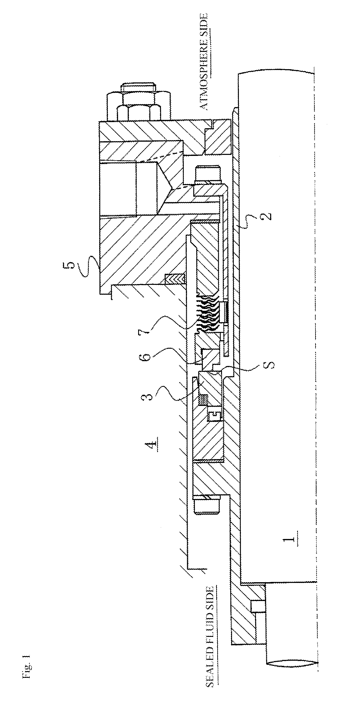
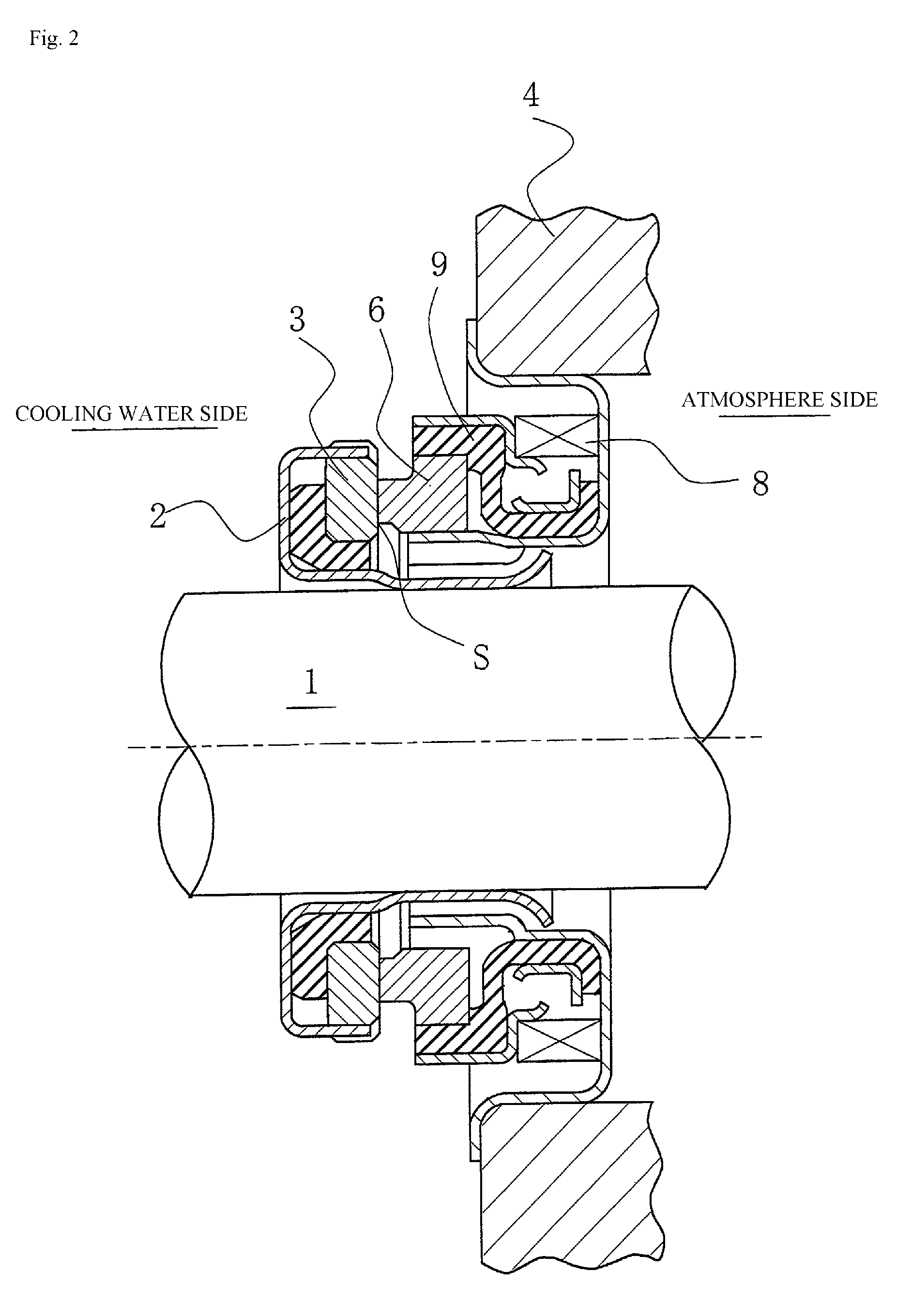
[0055]FIG. 3 is a plan view of one embodiment of the mechanical seal shown in FIGS. 1 and 2, in which pumping areas are formed on the sealing face S of the stationary ring 6, which has the smaller width with respect to the radial direction of the sealing faces of the stationary ring 6 and the rotating ring 3.

[0056]In FIG. 3, the stationary ring 6 is referred to as a seal ring, and is often formed from carbon (a soft material). A plurality of pumping areas 10 is discontinuously formed on the sealing face S of the stationary ring 6 in the circumferential direction so as to be a part of the radial direction of the sealing face S and directly communicate with the sealed fluid-containing space via an outer circumference side 12.

[0057]In the case of an outside-type mechanical seal in which the sealed fluid side is to the inside of the rotating ring 3 and the stationary ring 6, the pumping areas 10 need only be formed as part of the sealing face S in the radial direction and directly commu...

embodiment 2

[0097]FIG. 8 is a cross-sectional view of an instance in which, contrary to the first embodiment, pumping areas 10 are formed in a sealing face of a rotating ring 3 and dynamic pressure-generating grooves 20 are formed in a sealing face of a stationary ring 6 according to a second embodiment of the present invention.

[0098]In FIG. 8, the rotating ring 3 is referred to as a mating ring, and is often formed from SiC (a hard material). A plurality of pumping areas 10 is discontinuously formed in the circumferential direction of the sealing face S of the rotating ring 3. The plurality of pumping areas 10 is formed over a part of the outer and inner parts of the radial direction of the sealing face S, and is formed so that a part of the sealed fluid in the pumping areas 10 is not covered by the corresponding sealing face S of the stationary ring 6.

[0099]The stationary ring 6 is referred to as a seal ring, and is often formed from carbon (a soft material). Dynamic pressure-generating groov...

embodiment 3

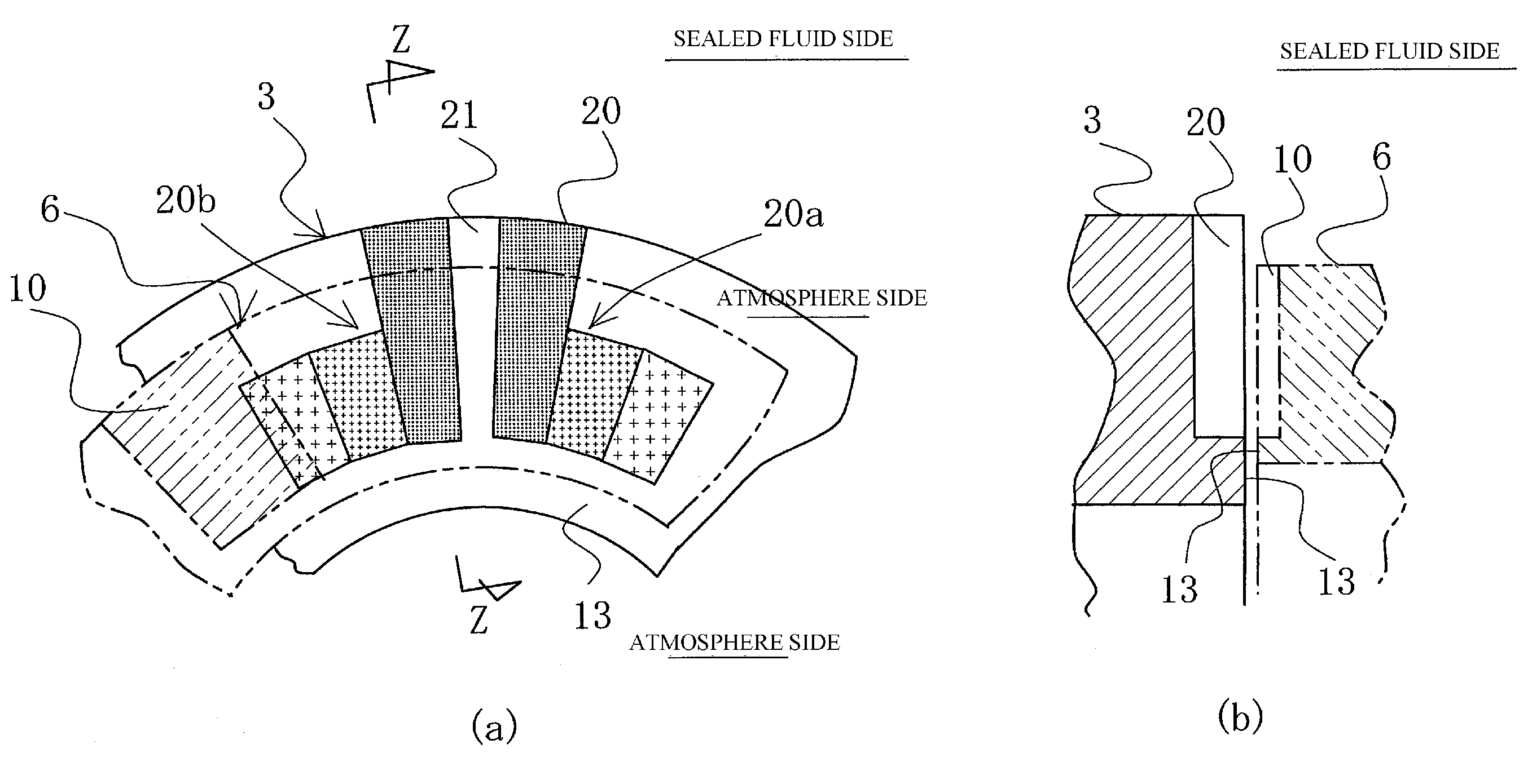
[0101]FIG. 9 is an illustration of another embodiment of pumping areas according to a third embodiment of the present invention, and is a cross-sectional view along a plane orthogonal to the sealing faces.

[0102]Whereas the pumping areas 10 are formed parallel to a plane orthogonal to the axis in the circumferential direction and the radial direction in the first embodiment, in FIG. 9, the intake pumping areas 10a are formed so that the linear indentations thereof grow progressively higher (shallower) towards the rotational direction R of the rotating ring 3 constituting the counterpart sliding member, and the outflow pumping areas 10b are formed so that the linear indentations thereof grow progressively lower (deeper) towards the rotational direction R of the rotating ring 3 constituting the counterpart sliding member.

[0103]Because the linear indentations are both inclined with respect to the rotation tangent line as seen in plan view and inclined in the circumferential direction as...


PUM


Abstract

Sliding parts are provided wherein a plurality of pumping areas for generating pumping action via the relative rotational sliding of a stationary ring and a rotating ring is discontinuously formed in a circumferential direction on a sealing face of one of the stationary ring and rotating ring so as to communicate with a sealed fluid-containing space. The pumping areas are provided with intake pumping areas operating in a direction in which the sealed fluid is drawn in and outflow pumping areas operating in a direction in which the sealed fluid is expelled. A plurality of dynamic pressure-generating grooves for generating dynamic pressure via the relative rotational sliding of the stationary ring and the rotating ring are formed in a circumferential direction on a sealing face of the other of the stationary ring and the rotating ring so as to communicate with the sealed fluid-containing space.

Description

[0001]This application is the U.S. National Phase under 35 U.S.C. §371 of International Application PCT / JP2012 / 070645, filed Aug. 13, 2012, which claims priority to Japanese Patent Application No. 2011-197731, filed Sep. 10, 2011. The International Application was published under PCT Article 21(2) in a language other than English.TECHNICAL FIELD[0002]The present invention relates to relatively rotating sliding parts, and in particular to sliding parts used, for example, in the field of automotive seals, general industrial mechanical seals, and other types of mechanical seals.BACKGROUND ART[0003]In sealing apparatuses for preventing the leakage of a sealed fluid, such apparatuses comprising two parts configured so as to rotate relatively to one another and so that end surfaces thereof slide along a plane, such as, for example, a mechanical seal, a balance must be struck between the two opposing conditions of seal tightness and lubrication in order to maintain seal integrity for exten...

Claims


Application Information

Patent Timeline
Patent Type & Authority Patents(United States)
IPC IPC(8): F16J15/40F16J15/34
CPCF16J15/40F16J15/342F16J15/3408F16J15/3412
Inventor HOSOE, TAKESHIINOUE, HIDEYUKI
Owner EAGLE INDS
Why Eureka
Try Eureka