Discharge lamp, light source device and projector

a technology of discharge lamp and light source device, which is applied in the direction of gas-filled discharge tube, lighting and heating apparatus, instruments, etc., can solve the problems of high viscosity and unyielding properties of glass, the crystallization of high-purity quartz glass is difficult, and the final crystallization (devitrification) is difficult, so as to achieve high display quality and reliability.

Active Publication Date: 2015-10-06
SEIKO EPSON CORP
View PDF24 Cites 0 Cited by
  • Summary
  • Abstract
  • Description
  • Claims
  • Application Information

AI Technical Summary

Benefits of technology

[0008]An advantage of some aspects of the invention is to provide a discharge lamp that may greatly improve the lamp life by effectively reducing devitrification of a discharge container and suppressing thinning of an electrode, and a projector using the lamp.

Problems solved by technology

The high-purity quartz glass has high viscosity and unyielding properties.
Further, the high-purity quartz glass is hard to be crystallized even at a high temperature and may secure sufficient light transmissivity in a certain period as the discharge container.
However, there has been a problem that, even in the case of using quartz glass, for use in a long time and a long period, it is finally crystallized (devitrified).
Further, there has been another problem that, with the use in a long time and a long period, an electrode made of tungsten becomes thinner.
However, according to this method, crystallization of the quartz glass may be suppressed to some degree, but, for example, the thinning of the tungsten electrode may not necessarily be suppressed.
In this case, the diffusion layer is formed by Si—B—O based glass and has not only high light transmissivity but also very good chemical stability and heat resistance, and thus, the layer is hard to be changed in properties even when exposed to a high temperature in use of the lamp.

Method used


Image

  • Discharge lamp, light source device and projector
  • Discharge lamp, light source device and projector
  • Discharge lamp, light source device and projector

Examples


working example

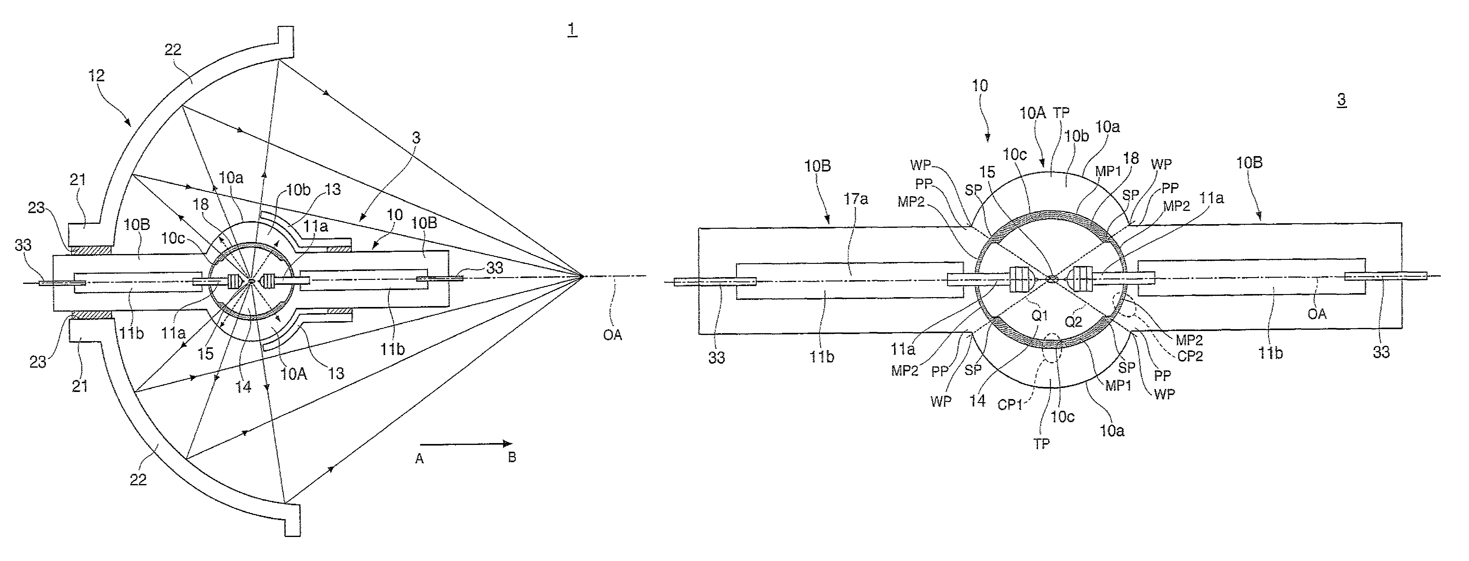
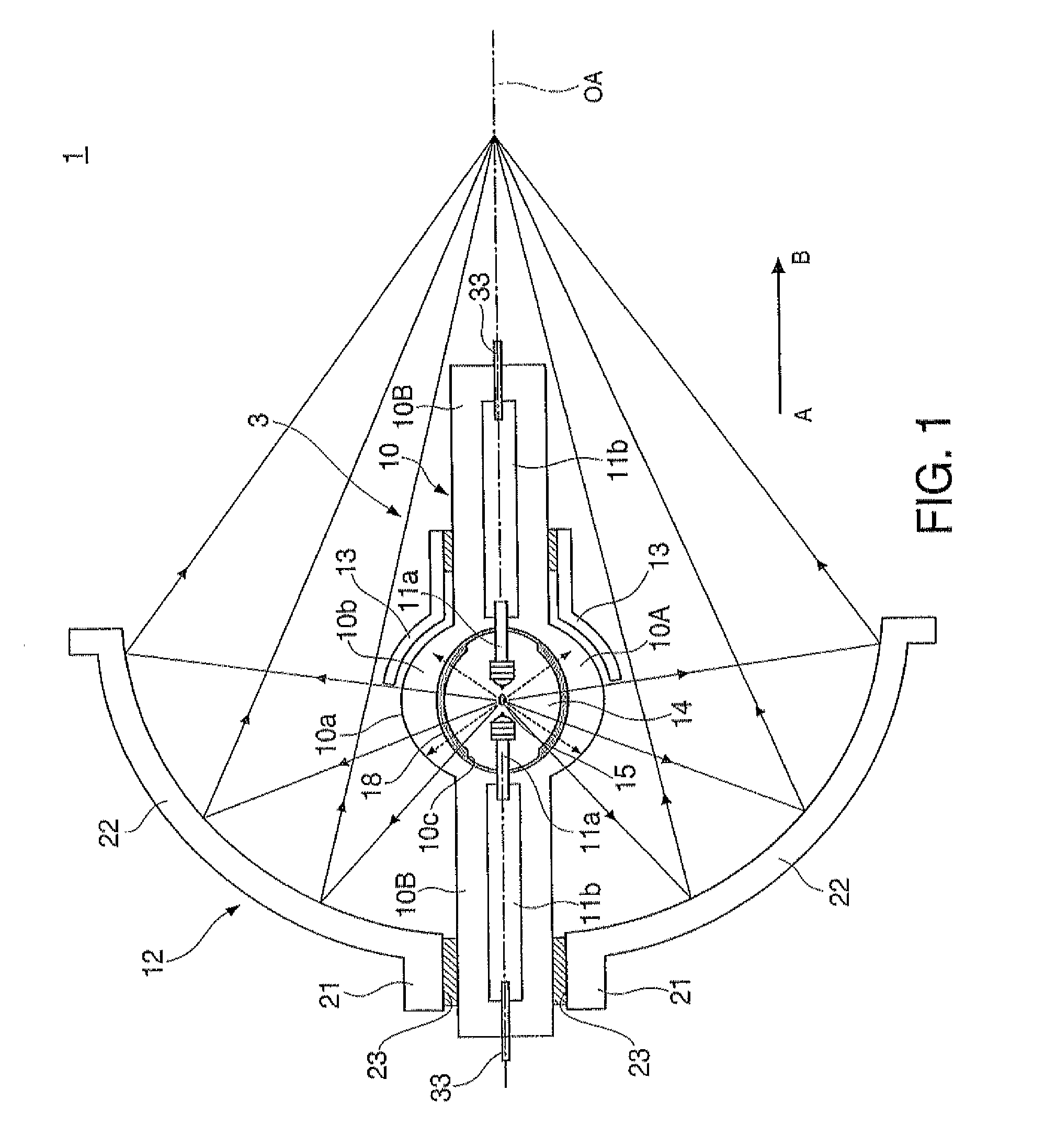
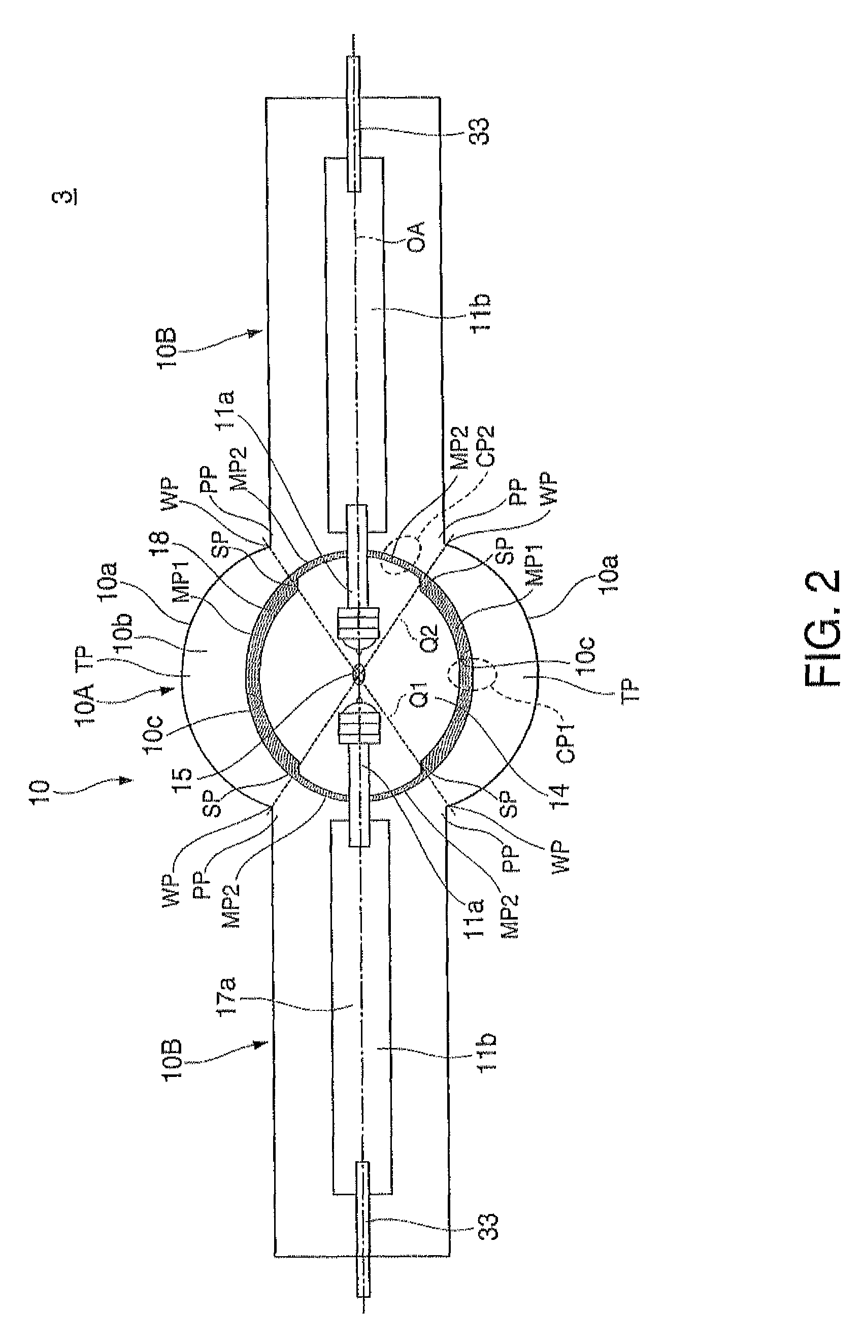
[0053]FIGS. 7A to 7C show states of changes of the electrode 11a with use of the discharge lamp 3. Specifically, FIG. 7A shows the shape of the electrode 11a after 307 hours from the start of use, FIG. 7B shows the shape after 539 hours from the start of use, and FIG. 7C shows the shape of the electrode 11a after 800 hours from the start of use. As shown in the pictures, in this case, slight deterioration is seen at the end of the electrode 11a, however, the axial side is kept to be thicker. On the other hand, in all of comparative examples shown in FIGS. 8A to 8I, the electrodes 11a are severely deteriorated. Specifically, FIG. 8A to 8C show changes of the electrode lla when the inner protective layer 18 is formed in a uniform thick film with no thickness difference in the discharge lamp 3. FIG. 8A to 8C show the electrode 11a after 261 hours, 450 hours, and 739 hours from the start of use, respectively. Similarly, FIG. 8D to 8F show changes of the electrode 11a when the inner prot...


PUM


Abstract

A discharge lamp includes a pair of electrodes for discharge and a discharge container having an inner space formed by quartz glass for separately placing the pair of electrodes and enclosing a discharge medium therein, a bulging part that surrounds the inner space, a pair of sealing parts that extend from ends of the bulging part and respectively support the pair of electrodes, an inner protective layer provided from a top portion opposed to a center of the pair of electrodes to a peripheral portion located at sides of the pair of sealing parts on an inner surface of the bulging part and having a thickness of the peripheral portion thinner than that of the top portion.

Description

CROSS-REFERENCE[0001]The entire disclosure of Japanese Patent Application No. 2011-17638, filed Jan. 31, 2011 is expressly incorporated by reference herein.BACKGROUND[0002]1. Technical Field[0003]The present invention relates to a discharge lamp having a discharge container made of quartz glass, and a light source device and a projector using the same.[0004]2. Related Art[0005]For a light source device used in a projector, for example, a discharge lamp such as an ultra-high pressure mercury lamp is mainly used. For a discharge container forming the discharge lamp, high-purity quartz glass is often used. The high-purity quartz glass has high viscosity and unyielding properties. Further, the high-purity quartz glass is hard to be crystallized even at a high temperature and may secure sufficient light transmissivity in a certain period as the discharge container.[0006]However, there has been a problem that, even in the case of using quartz glass, for use in a long time and a long perio...

Claims


Application Information

Patent Timeline
Patent Type & Authority Patents(United States)
IPC IPC(8): H01J17/16H01J61/35G03B21/20H01J61/04H01J61/82F21Y101/00
CPCG03B21/2026H01J61/045H01J61/35H01J61/827
Inventor NISHIYAMA, YOSHIHIDE
Owner SEIKO EPSON CORP
Why Eureka
Try Eureka