Polyaxial pedicle screw and fixation system kit comprising the screw

a technology of pedicle screw and screw, which is applied in the field of orthopaedic surgical implants, can solve the problems of limiting the freedom of surgeons in tightening and loosening the elements, limiting the freedom of surgeons in adjusting the shank orientation during minimal invasive surgery, and unable to lock the relative orientation of the shank before rod insertion, etc., and achieves the effect of minimal invasive techniques

Active Publication Date: 2015-10-13
MEDACTA INT SA
View PDF15 Cites 32 Cited by
  • Summary
  • Abstract
  • Description
  • Claims
  • Application Information

AI Technical Summary

Benefits of technology

[0011]Another object of the present invention is that of allowing the surgeon to lock the relative orientation of the shank before rod insertion in minimal invasive surgery and / or deformative correction.
[0015]In particular, the locking insert may exhibit an elongated shape with two lateral arms extending through the lateral apertures, but without projecting out of the receiving head, the distal sides of the lateral arms defining the contact surface. In this embodiment, the lateral apertures may advantageously restrain the motion of the lateral arms of the locking insert in a distal direction.
[0016]Also, the receiving head may comprise two (or more) lateral longitudinal grooves opening on the through bore, the lateral longitudinal grooves defining longitudinal paths for the external pressing action. In such a way, the external pressing action extending through the longitudinal grooves may advantageously contact the lateral arms of the locking insert without projecting from the cross-section of the device, allowing minimally invasive techniques to be employed. The lateral arms may even have lateral extensions projecting out of the receiving head, but what may be helpful is that the distal sides of these lateral arms may offer a contact surface for the external pressing action.

Problems solved by technology

However, due to the irregularity of bone anatomy, it is unlikely that once the screws have been implanted into the spine pedicles, their heads will be properly aligned for rod insertion.
However, such an arrangement may oblige the surgeon to insert the connecting rod while the screw head is freely rotatable with respect to the shank, which may be prejudicial to an optimal placement of the fixation system.
As will be appreciated by those skilled in the art, spinal surgery, especially when adopting minimal invasive techniques, may be challenging and may be important to provide freedom of placement of the fixation systems together with ease of intervention.
However, such an approach does not allow the surgeon to correct the shank orientation during or after insertion of the connecting rod, since he would be unable to loosen the locking insert when the rod is placed upon it.
However, the presence of the outer set-screw prevents insertion of the connecting rod from above, and as a consequence, the surgeon cannot lock the relative orientation of the shank before rod insertion in minimal invasive surgery.
However, this instrument has to be removed before insertion of the set-screw clamping the rod, once again limiting the surgeon's freedom in tightening and loosening the elements while looking for the best possible arrangement for the fixation system.
However, such an arrangement may significantly increase the lateral profile of the fixation system, and may not suitable for traditional surgery techniques.
Moreover, the position of the rod being off-set from the screw axis, the screw is also unsuitable for minimal invasive and deformity correction surgeries.

Method used


Image

  • Polyaxial pedicle screw and fixation system kit comprising the screw
  • Polyaxial pedicle screw and fixation system kit comprising the screw
  • Polyaxial pedicle screw and fixation system kit comprising the screw

Examples


Embodiment Construction

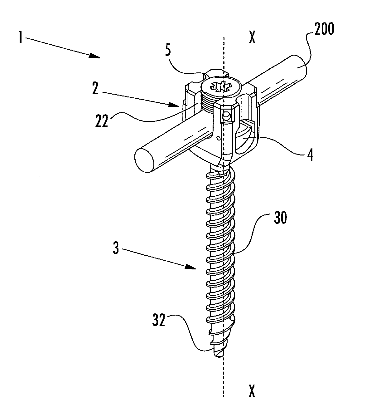
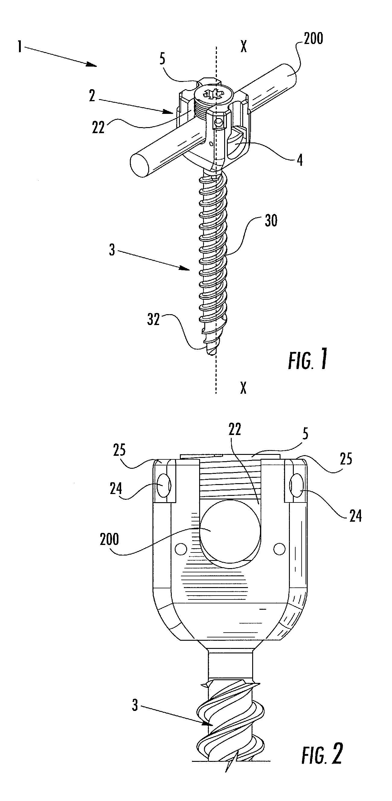
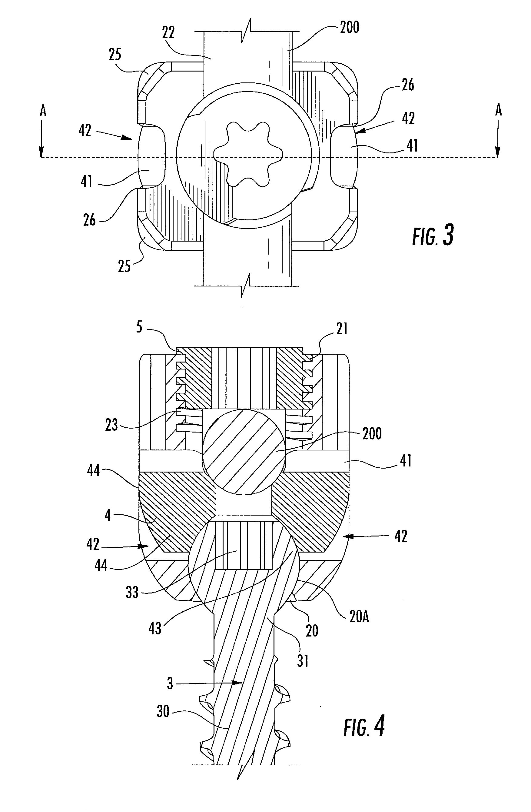
[0030]Referring to FIGS. 1-4, a polyaxial pedicle screw 1 is illustrated according to the present invention. A plurality of such screws 1, along with connecting rods 200, form a fixation system for spinal surgery, which may be sold in a kit together with a locking instrument 100 as depicted in FIGS. 5-6. The polyaxial pedicle screw 1 comprises a shank 3 having a threaded portion 30 and a bulging end 31. The screw 1 may be cannulated or fenestrated without departing from the principles of the present invention. The screw may even be conical or straight and may be coated with an appropriate coating according to the application purposes.

[0031]The threaded portion 30, provided with a single or multiple lead threading and ending with a tip 32, is adapted for insertion and secure anchorage in the vertebral pedicle of a patient. In one embodiment, a dual lead thread is provided. The bulging end 31 has a substantially spherical shape, with a flat distal end featuring a socket 33 able to mat...


PUM


Abstract

A polyaxial pedicle screw may include a receiving head having a transversal U-shaped passage, and a shank having a threaded portion external to the receiving head, and a bulging end rotatable housed within the receiving head. The polyaxial pedicle screw may include a locking insert housed within the receiving head and matable with the bulging end, for locking it into position, and a set-screw engaged in the distal aperture for locking a connecting rod received within the transversal U-shaped passage. The receiving head of the polyaxial screw may include a lateral aperture, the lateral aperture exposing a contact surface of the locking insert in such a way that external pressing component can act on the contact surface to maintain the locking insert into its locking position.

Description

FIELD OF THE INVENTION[0001]The present invention relates to the general field of orthopedic surgical implants, more specifically, a polyaxial pedicle screw being part of a pedicle screw fixation system, used in the field of surgical spine treatment.BACKGROUND OF THE INVENTION[0002]Surgical techniques for the treatment of spinal injuries or deformities are usually aimed at joining together two or more vertebrae of the spine, through a process that is called spinal fusion. A possible approach to spinal fusion adopts a fixation system that is anchored to the spine by way of orthopedic screws implanted into the pedicles of two or more subsequent vertebrae. The single screws are connected together by means of rigid or semi-rigid rods, which are conveniently housed within a transversal hole provided in the screw head.[0003]However, due to the irregularity of bone anatomy, it is unlikely that once the screws have been implanted into the spine pedicles, their heads will be properly aligned...

Claims


Application Information

Patent Timeline
Patent Type & Authority Patents(United States)
IPC IPC(8): A61B17/70
CPCA61B17/7035A61B17/7082A61B17/7037A61B17/7076
Inventor AUERBACH, JOSHUA D.FEKETE, ZSOLTFIECHTER, MEINRADHEYDE, CHRISTOPH E.SICCARDI, FRANCESCO
Owner MEDACTA INT SA
Why Eureka
Try Eureka