Wireless power charging using point of load controlled high frequency power converters

a high-frequency power converter and wireless power technology, applied in charging stations, electric devices, transportation and packaging, etc., can solve the problems of high loss, lower performance than tolerable, and loss in the primary coil itsel

Active Publication Date: 2015-10-13
UT BATTELLE LLC
View PDF12 Cites 97 Cited by
  • Summary
  • Abstract
  • Description
  • Claims
  • Application Information

AI Technical Summary

Benefits of technology

[0018]The present disclosure provides a wireless power transfer charging system including a point of load control, and a method for operating the same. An apparatus for wirelessly charging a battery of an electric vehicle comprises a base unit for generating a direct current (DC) voltage. The base unit is regulated by a power level controller. Also, one or more point of load converters can be connected to the base unit by a conductor, with each point of load converter comprising a control signal generator that transmits a signal to the power level controller. The output power level of the DC voltage provided by the base unit is controlled by power level controller such that the power level is sufficient to power all active load converters when commanded to do so by any of the active controllers, without generating excessive power that may be otherwise wasted.

Problems solved by technology

Another aspect of the WPT efficiency challenge is coupling coil conductor type and design.
This raises a concern that a cable connecting the Wireless Power Transfer Base Converter (WPTB) to a primary coil on a residential garage floor for example would have wire mesh or rebar in the concrete below, which may lead to high losses and lower performance than tolerable.
Additionally, loss is incurred in the primary coil itself due to skin and proximity effects.

Method used


Image

  • Wireless power charging using point of load controlled high frequency power converters
  • Wireless power charging using point of load controlled high frequency power converters
  • Wireless power charging using point of load controlled high frequency power converters

Examples


Embodiment Construction

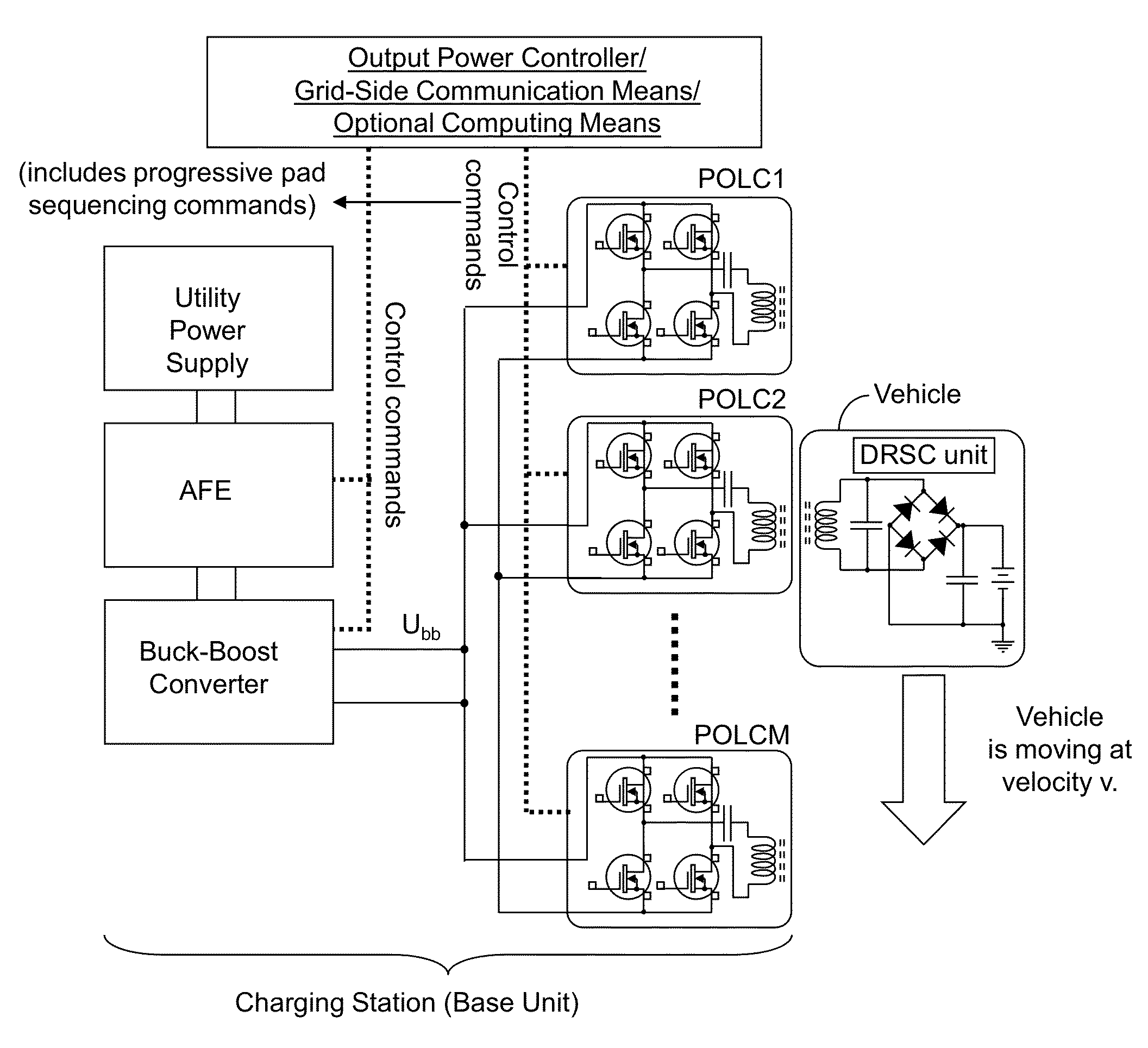
[0033]As stated above, the present invention relates to stationary and dynamic wireless power chargers for use in charging plug-in electric vehicles, and methods of operating the same, which is now described in detail with accompanying figures. The drawings are not drawn to scale.

[0034]Examples of wireless power transfer devices are described in: U.S. Patent Application Publication No. 2012 / 0043930 A1 published on Feb. 12, 2012 and issued as U.S. Pat. No. 8,310,202 on Nov. 13, 2012, and U.S. Provisional Patent Application Ser. Nos. 61 / 510,231, filed Jul. 21, 2011; 61 / 510,210, filed Jul. 21, 2011; 61 / 510,206, filed Jul. 21, 2011; and 61 / 532,763, filed Sep. 9, 2011, each of which are incorporated herein by reference. Further, U.S. patent application Ser. No. 13 / 484,404 titled “REGULATION CONTROL AND ENERGY MANAGEMENT SCHEME FOR WIRELESS POWER TRANSFER” and filed on May 31, 2012 is incorporated herein by reference.

[0035]As used herein, “wireless power transfer” refers to the transmissi...


PUM


Abstract

An apparatus for wirelessly charging a battery of an electric vehicle is provided with a point of load control. The apparatus includes a base unit for generating a direct current (DC) voltage. The base unit is regulated by a power level controller. One or more point of load converters can be connected to the base unit by a conductor, with each point of load converter comprising a control signal generator that transmits a signal to the power level controller. The output power level of the DC voltage provided by the base unit is controlled by power level controller such that the power level is sufficient to power all active load converters when commanded to do so by any of the active controllers, without generating excessive power that may be otherwise wasted.

Description

CROSS-REFERENCE TO RELATED APPLICATIONS[0001]This application claims the benefit of priority from U.S. provisional application No. 61 / 598,387, filed on Feb. 14, 2012, the contents of which are incorporated herein by reference.STATEMENT REGARDING FEDERALLY SPONSORED RESEARCH OR DEVELOPMENT[0002]This invention was made with government support under Contract No. DE-AC05-000R22725 awarded by the U.S. Department of Energy. The government has certain rights in the invention.FIELD OF THE INVENTION[0003]The present invention relates to the field of wireless power transfer, and particularly to stationary and dynamic wireless power chargers for use in charging plug-in electric vehicles, and methods of operating the same.BACKGROUND OF THE INVENTION[0004]Plug-in Electric Vehicles (PEV) utilize a battery to store energy and power an electric motor to provide propulsion. When the battery becomes depleted, a PEV must be recharged for a period of time. Recharging may be performed by plugging the ve...

Claims


Application Information

Patent Timeline
Patent Type & Authority Patents(United States)
IPC IPC(8): B60L11/18H02J7/02H02J5/00H02J17/00
CPCB60L11/182H02J5/005H02J7/025H02J17/00Y02T90/14Y02T10/7005Y02T90/122Y02T10/7072B60L53/122B60L53/126H02J2310/48Y02T10/70H02J50/402H02J50/80H02J7/0048H02J50/12Y02T90/12B60L53/12
Inventor MILLER, JOHN M.CAMPBELL, STEVEN L.CHAMBON, PAUL H.SEIBER, LARRY E.WHITE, CLIFFORD P.
Owner UT BATTELLE LLC
Why Eureka
Try Eureka