
Peripheral tunnels propeller

a propeller and tunnel technology, applied in the direction of rotary propellers, air transport, climate sustainability, etc., can solve the problems of parasite shock waves on the fluid, and achieve the effects of avoiding water agitation, minimizing turbulence, and minimizing turbulen

Inactive Publication Date: 2015-10-13
ACOSTA JOSE ANGEL
View PDF23 Cites 0 Cited by
  • Summary
  • Abstract
  • Description
  • Claims
  • Application Information

AI Technical Summary

Benefits of technology

The present invention achieves noise abatement by displacing fluid into multiple rotating cylindrical chambers with circular cross-sections. These chambers minimize turbulence and agitation caused by hitting against the walls, resulting in minimal fluid turbulence and reduced noise. The use of a cylinder as a fluid container also avoids agitation of the perpendicular momentum of the fluid, resulting in continuous fluid movement with minimal turbulence.

Problems solved by technology

Such fluid momentum caused by each creates turbulence and parasite shock waves on the fluid.

Method used


Image

  • Peripheral tunnels propeller
  • Peripheral tunnels propeller
  • Peripheral tunnels propeller

Examples


Embodiment Construction

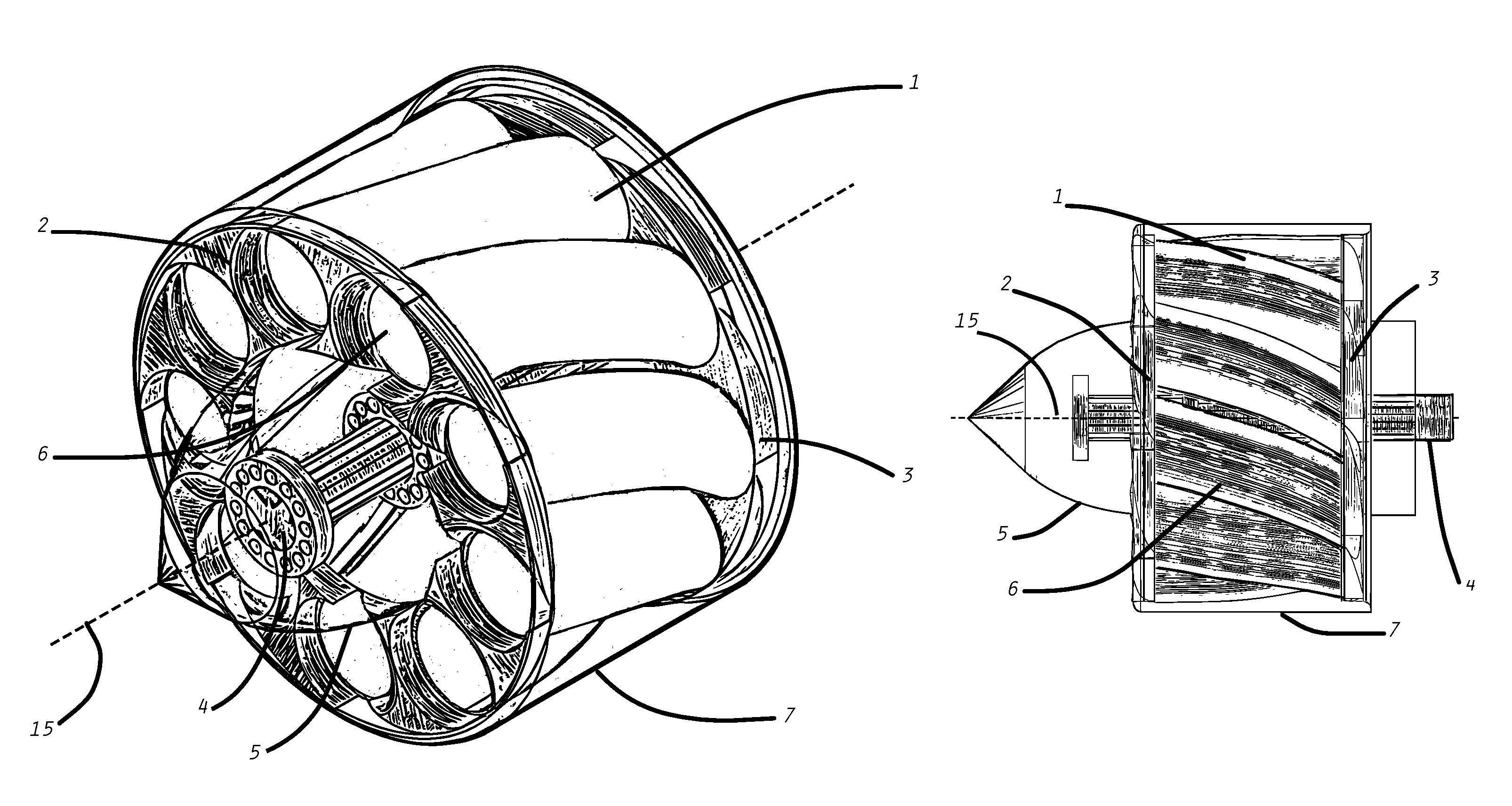
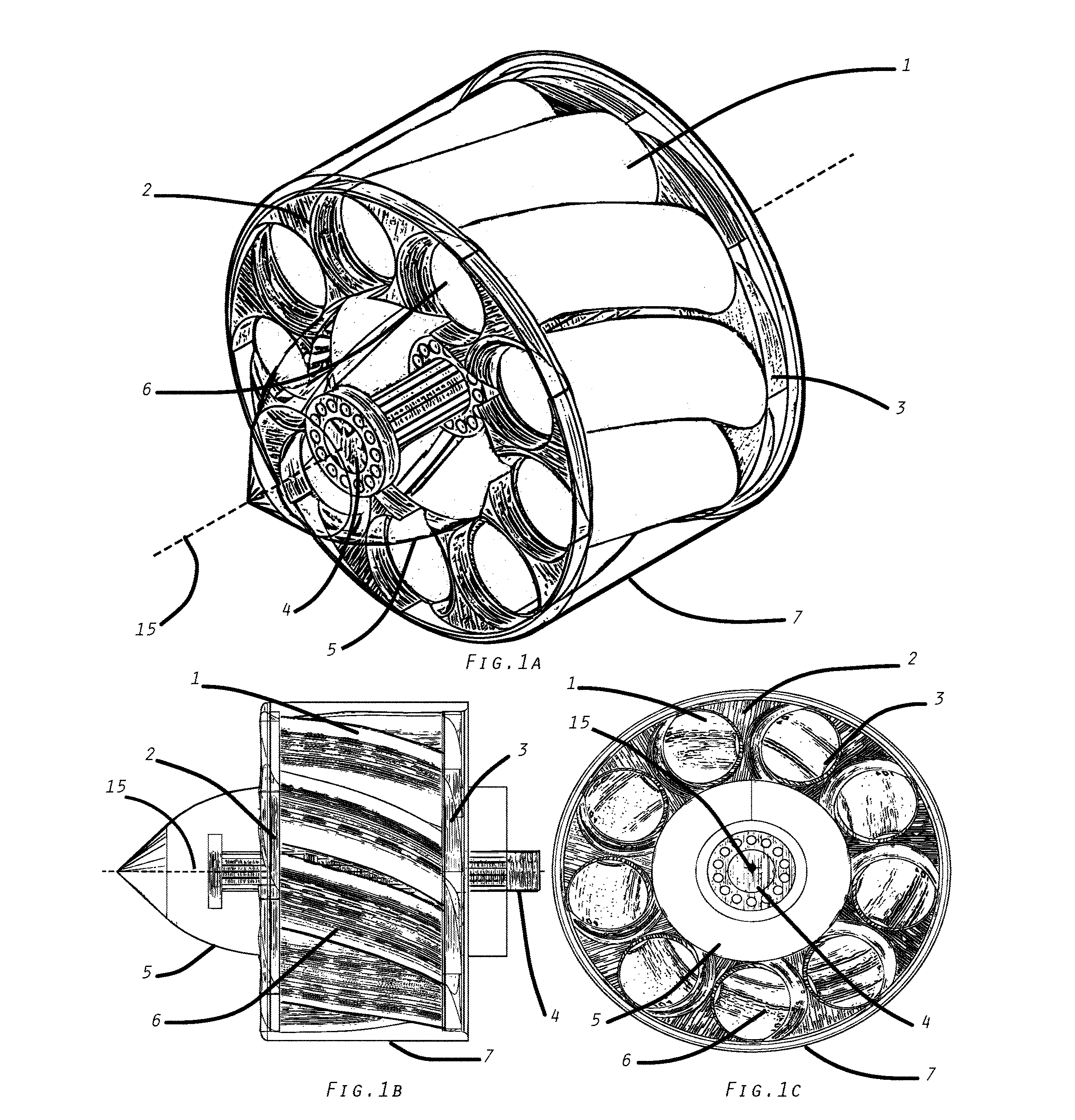
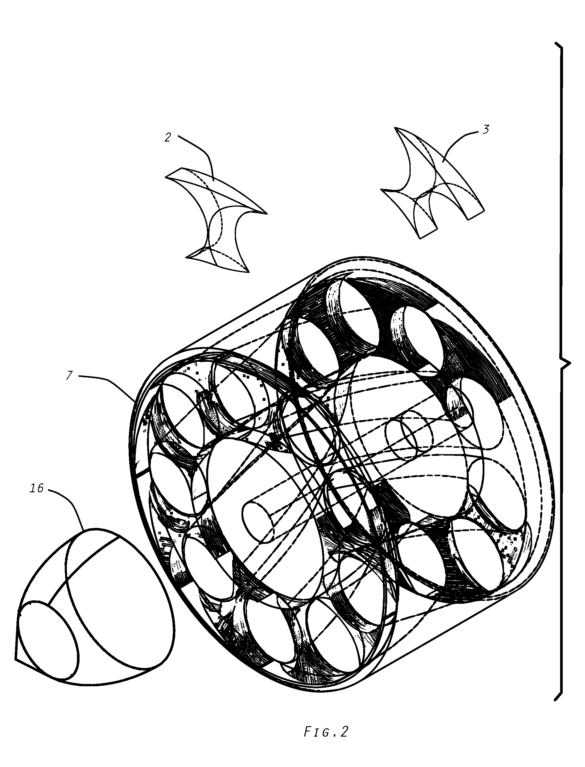
[0019]Referring now to the drawings in more detail, in FIG. 1a to FIG. 1c there is shown a cylindrical block 7 having, in its preferred embodiment, multiple peripheral holes as spiraling tunnels with inlet and outlet ends. An inner shaft 4 provides rotation guide and torque to spin the cylindrical block. Fluid guide structures 2, 3 are located at each end. The cylindrical structure further includes a conical or spherical structure 5 mounted to the outlet end.

[0020]In more detail, still referring to the invention of FIG. 1a to FIG. 1c, tunnels 1 are aligned at the same radius for a single row of tunnels or at various radii for multiple rows of tunnels. Each tunnel has a virtual center axis that describes a spiral extending from the inlet end to the outlet end. Each spiral, in the preferred embodiment, may only reach a fraction of the turn at which point the center radius may vary as the tunnel reaches the output side.

[0021]Depending on the fluid viscosity and the final speed of the p...


PUM


Abstract

This disclosure is related with propeller noise and cavitation abatement in applications like propulsion, ventilation, pumping or turbine systems on liquid or gas fluids working like a propellers, pumps, fans or turbines, by novel techniques that allows a stronger propellers and improves laminar flow and allow a smooth acceleration or deceleration of the liquid or gas by means of a propeller that consist on a rotating cylindrical block with one or more tunnels around it axis, said cylindrical block also may have flow separators structures at both input and output that helps to keep laminar flow of the fluid or gas with it surrounding media, having This rotating cylindrical block tunnels with either circular or irregular oval section that accelerates fluid or gas by means of both combined centrifugal and axial movement.

Description

CROSS-REFERENCE TO RELATED APPLICATIONS[0001]Provisional application No. 61 / 228,133 Filed on Jul. 23, 2009BACKGROUND OF THE INVENTION[0002]1. Field of Invention[0003]The invention disclosed herein relates to propeller improvement, particularly to noise and cavitation abatement on propellers used on marine propulsion, fluid pumps, fans, and power turbines. Noise is always undesirable collateral of machine function, is source of illness, operational restrictions, and service life shortened on devices affected by noise. It is also a security concern to deal with when discrete operation is required.[0004]2. Discussion of the Prior Art[0005]Propellers accelerate a fluid by impinging it against a rotating blade. Such acceleration provides the thrust to an object to which it is connected. A common cause of noise is created by the turbulence of the fluid, cavitation and the vibration of the propellers' blades. Some designs achieve lower noise by means of a hardened blade structure, or surro...

Claims


Application Information

Patent Timeline
Patent Type & Authority Patents(United States)
IPC IPC(8): B63H1/16F01D1/34B63H1/12F04D29/44
CPCF01D1/34B63H1/12F04D29/442F04D29/447Y02T50/672F05D2250/14F05D2250/141F05D2250/231F04D29/181F04D29/325Y02T50/60
Inventor ACOSTA, JOSE ANGEL
Owner ACOSTA JOSE ANGEL
Learn More