Ported shroud geometry to reduce blade-pass noise

a technology of blade-pass and shroud, which is applied in the direction of machines/engines, liquid fuel engines, mechanical equipment, etc., can solve the problems of not helping minimize turbulence or noise, causing audible noise, and causing turbulence in the vicinity of the operating vehicle, so as to reduce the turbulence in the portion of airflow which flows through the recirculation cavity, reduce the turbulence in the airflow, and reduce the turbulence in the noise of nois

Active Publication Date: 2018-04-24
BORGWARNER INC
View PDF22 Cites 20 Cited by
  • Summary
  • Abstract
  • Description
  • Claims
  • Application Information

AI Technical Summary

Benefits of technology

[0008]In accordance with another aspect of the disclosure, a turbocharger is disclosed. The turbocharger may be configured to include a turbine wheel and a compressor wheel. Moreover, the turbocharger may further include a shaft which rotatably connects the turbine wheel and the compressor wheel. The turbocharger may further include a compressor housing enclosing the compressor wheel and an inlet portion formed in the compressor housing which may be configured to direct an airflow towards the compressor wheel. The turbocharger may further include a shroud portion which is integrated with the compressor housing and configured to circumferentially surround the compressor wheel and a volute portion in fluid communication with the compressor wheel defining an output airflow pathway of the turbocharger. The turbocharger may further include a recirculation cavity which is formed within the compressor housing and positioned between an exterior surface of the shroud portion and an interior surface of the compressor housing such that the recirculation cavity being in fluid communication with the inlet portion. Moreover a recirculation slot may define an airflow pathway between the recirculation cavity and the compressor wheel. The turbocharger may further include an angled shroud support which extends radially through the recirculation cavity from the exterior surface of the shroud portion to the interior surface of the compressor housing. Moreover, the angled shroud support may be spaced an axial distance away from the recirculation slot to minimize turbulence in the airflow as it moves from the recirculation cavity to the compressor wheel.
[0009]In accordance with a further aspect of the disclosure a method of reducing airflow turbulence and noise through a compressor is disclosed. The method may include fabricating a compressor housing which includes an inlet portion and a shroud portion. Moreover the inlet portion may be configured to direct an airflow through the shroud portion towards a compressor wheel. The method may further include forming a recirculation cavity between an exterior surface of the shroud portion and an interior surface of the compressor housing. Moreover, the shroud portion may be supported by radially extending an angled shroud support between the exterior surface of the shroud portion and the interior surface of the compressor housing. The method may further include directing a portion of the airflow form the inlet portion into an airflow pathway which flows through the recirculation cavity. Moreover the portion of airflow may be split along the angled shroud support as the portion of airflow travels through the airflow pathway. Moreover, turbulence in the portion of airflow which flows through the recirculation cavity may be reduced by spacing the angled shroud support an axial distance away from a recirculation slot such that the portion of airflow split by the angled shroud support recombines and flows the axial distance towards the recirculation slot and is delivered to the compressor wheel.

Problems solved by technology

Furthermore, during certain compressor operating conditions, such as but not limited to periods of maximum flow capacity, the interaction between the incoming air and rotating compressor wheel produces an audible noise source which may be unacceptable to vehicle passengers and other individuals in the vicinity of the operating vehicle.
While such helical pathway may help in directing certain portions of the airflow they do not help minimize the turbulence or minimize noise.

Method used


Image

  • Ported shroud geometry to reduce blade-pass noise
  • Ported shroud geometry to reduce blade-pass noise
  • Ported shroud geometry to reduce blade-pass noise

Examples


Embodiment Construction

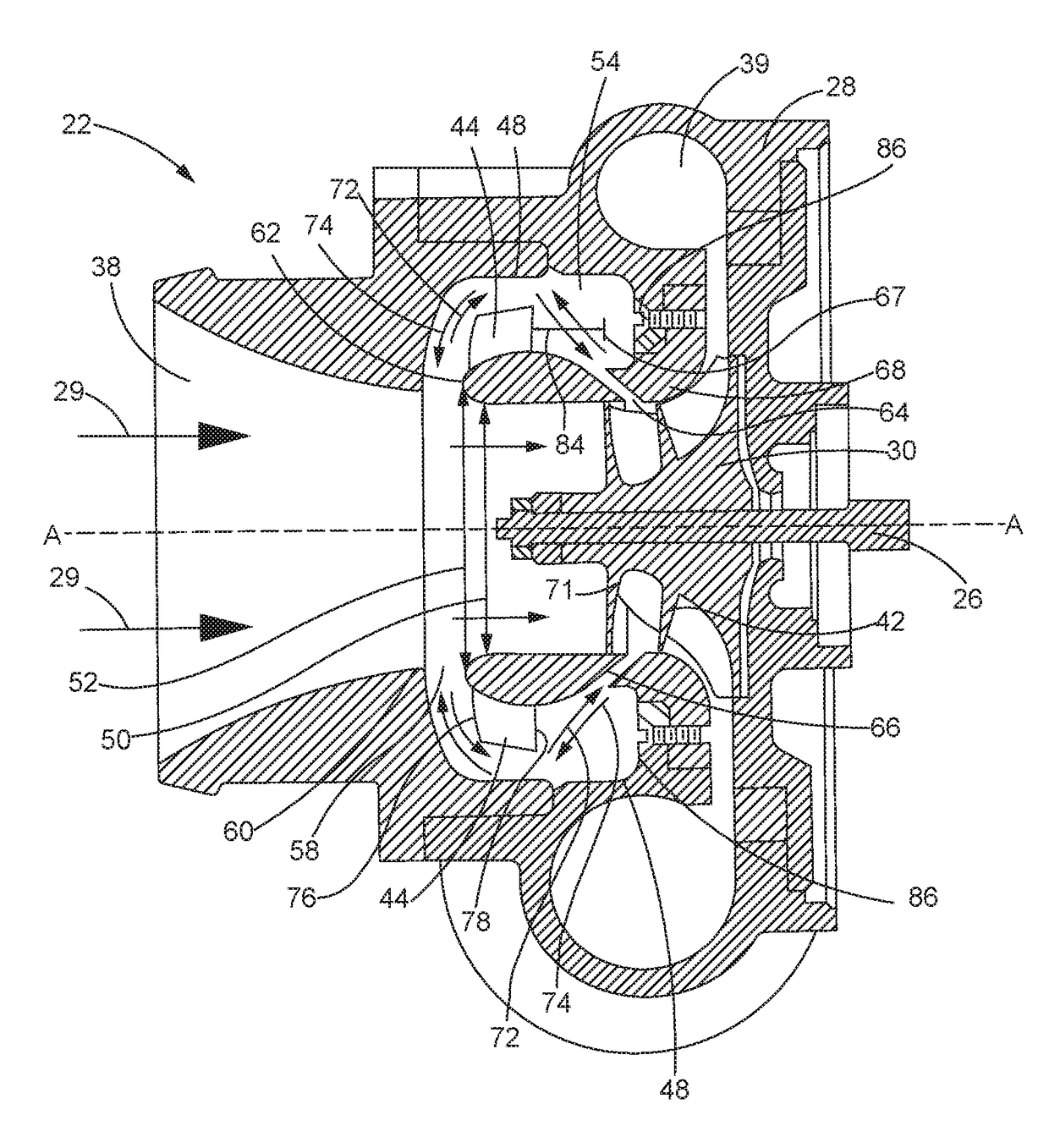
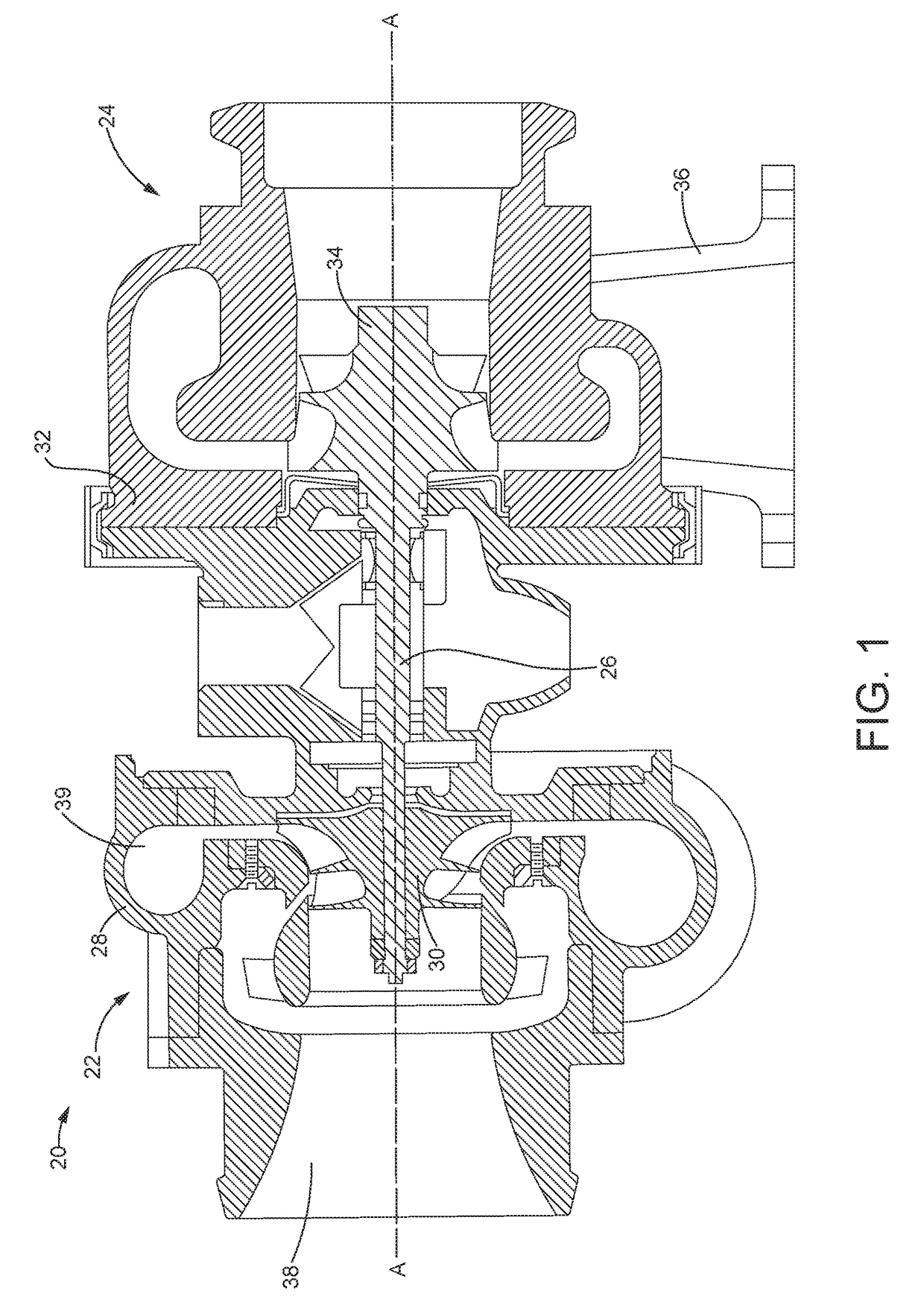
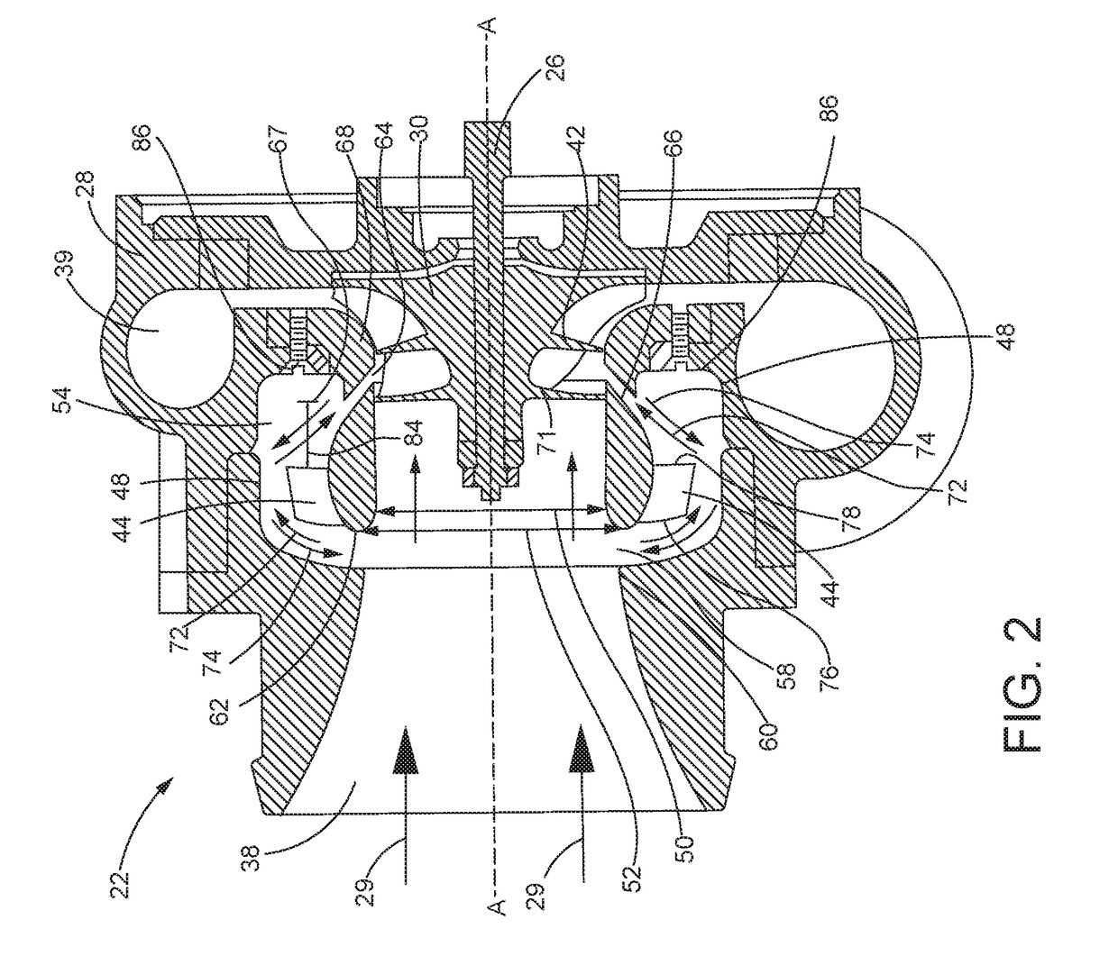
[0018]Referring now to FIG. 1, an exemplary turbocharger 20 is shown. In one non-limiting example, the turbocharger 20 may include a compressor portion 22 and a turbine portion 24. In some embodiments, the compressor portion 22 and the turbine portion 24 may be rotatably connected a rotatable shaft 26. Furthermore, the compressor portion 22 may include a compressor housing 28 and a compressor wheel 30 that is disposed within the compressor housing 28. Additionally, the turbine portion 24 may include a turbine housing 32 and a turbine wheel 34 that is disposed within the turbine housing 32. Moreover, the compressor wheel 30 and the turbine wheel 34 may be disposed on opposite ends of the rotatable shaft 26. In some embodiments, the rotatable shaft 26, the compressor wheel 30, and the turbine wheel 34 are rotatable along an axis A-A of the turbocharger 20.

[0019]Furthermore, the turbine wheel 34 may be rotatably driven by an inflow of air or gas which is supplied through an exhaust gas...


PUM


Abstract

A compressor housing may include a shroud portion which is axially spaced from an inlet portion and configured to at least partially surround the compressor wheel. The compressor housing may be further configured to include a recirculation cavity which is formed between an exterior surface of the shroud portion and an interior surface of the compressor housing. Furthermore, a recirculation slot may define an airflow pathway between the recirculation cavity and the compressor wheel. Additionally, the compressor housing may include an angled shroud support extending radially through the recirculation cavity from the exterior surface of the shroud portion to the interior surface of the compressor housing. The angled shroud support may be spaced an axial distance away from the recirculation slot to reduce turbulence in the airflow as the airflow moves from the recirculation cavity to the compressor wheel.

Description

TECHNICAL FIELD[0001]The present disclosure relates generally a turbocharger, and more specifically to a ported shroud for a compressor housing incorporated with the turbocharger.BACKGROUND[0002]Turbochargers used with engines, such as internal combustion engines, generally provide compressed air to an engine intake. The compressed air may allow additional fuel to be combusted within the engine cylinders, and, therefore the engine's horsepower may be increased while keeping the engine substantially the same size. As such, incorporating turbochargers into internal combustion engines may allow for smaller engines to be used without sacrificing the engine horsepower. Furthermore, using a turbocharger may help improve fuel economy, reduce engine emissions, and increase overall engine efficiency by providing more complete combustion of the fuel injected into the engine cylinders.[0003]In general, a turbocharger typically includes a turbine housing connected to the engine's exhaust manifo...

Claims


Application Information

Patent Timeline
Patent Type & Authority Patents(United States)
IPC IPC(8): F04D29/66F02B37/00F04D29/42F04D29/28F04D29/053F04D27/00F04D17/10F01D5/02F02B33/40F04D29/44
CPCF04D29/665F01D5/02F02B33/40F02B37/00F04D17/10F04D29/053F04D29/284F04D29/4233F04D29/441F04D27/009F05D2230/50F05D2220/40F04D25/024F04D29/4213F04D29/681F04D29/685Y02T10/12
Inventor LUCAS, EVAN
Owner BORGWARNER INC
Why Eureka
Try Eureka