Interconnected microchannel tube

a microchannel tube and interconnection technology, applied in the direction of tubular elements, lighting and heating apparatus, laminated elements, etc., can solve the problems of unfavorable heat transfer of the front edge of the tube, undetected large pressure drop, and create turbulent flow, so as to improve the heat transfer of the tube and minimize the effect of turbulen

Inactive Publication Date: 2005-11-03
OUTOKUMPU OY
View PDF20 Cites 21 Cited by
  • Summary
  • Abstract
  • Description
  • Claims
  • Application Information

AI Technical Summary

Benefits of technology

[0012] Another embodiment of the invention relates to an improvement in a heat exchanger that includes a plurality of microchannels therein and through which a heat transfer medium flows. The improvement comprises providing a plurality of openings in the microchannels, such that the heat transfer medium can flow in a laminar manner between the microchannels thereby permitting mixing of liquid and vapor phases of the heat transfer medium for improved heat transfer of the tube. The fluid passes between the microchannels without encountering obstructions to minimize turbulence in the fluid.

Problems solved by technology

This creates a heat transfer imbalance between the front edge of the tube to the leeway side of the tube, in lieu of the flow direction of the external heat transfer medium.
These openings would create undesirably large pressure drops and create turbulent flow in the heat transfer medium.
Thus, construction of the Shimizu et al. tube is relatively complex.

Method used


Image

  • Interconnected microchannel tube
  • Interconnected microchannel tube
  • Interconnected microchannel tube

Examples


Embodiment Construction

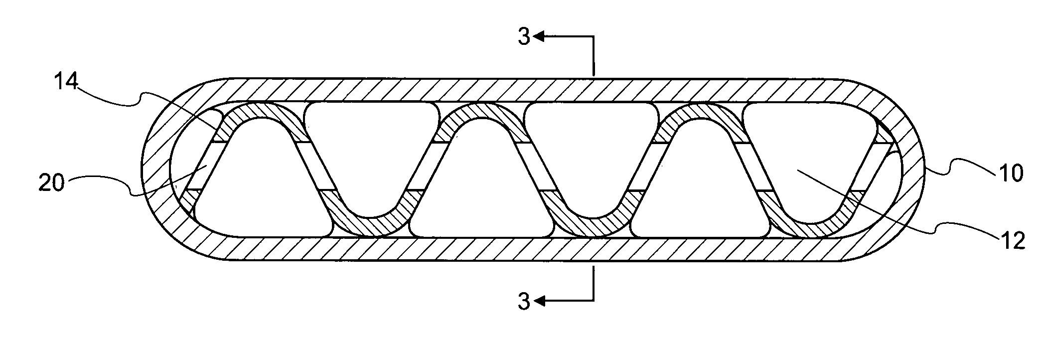
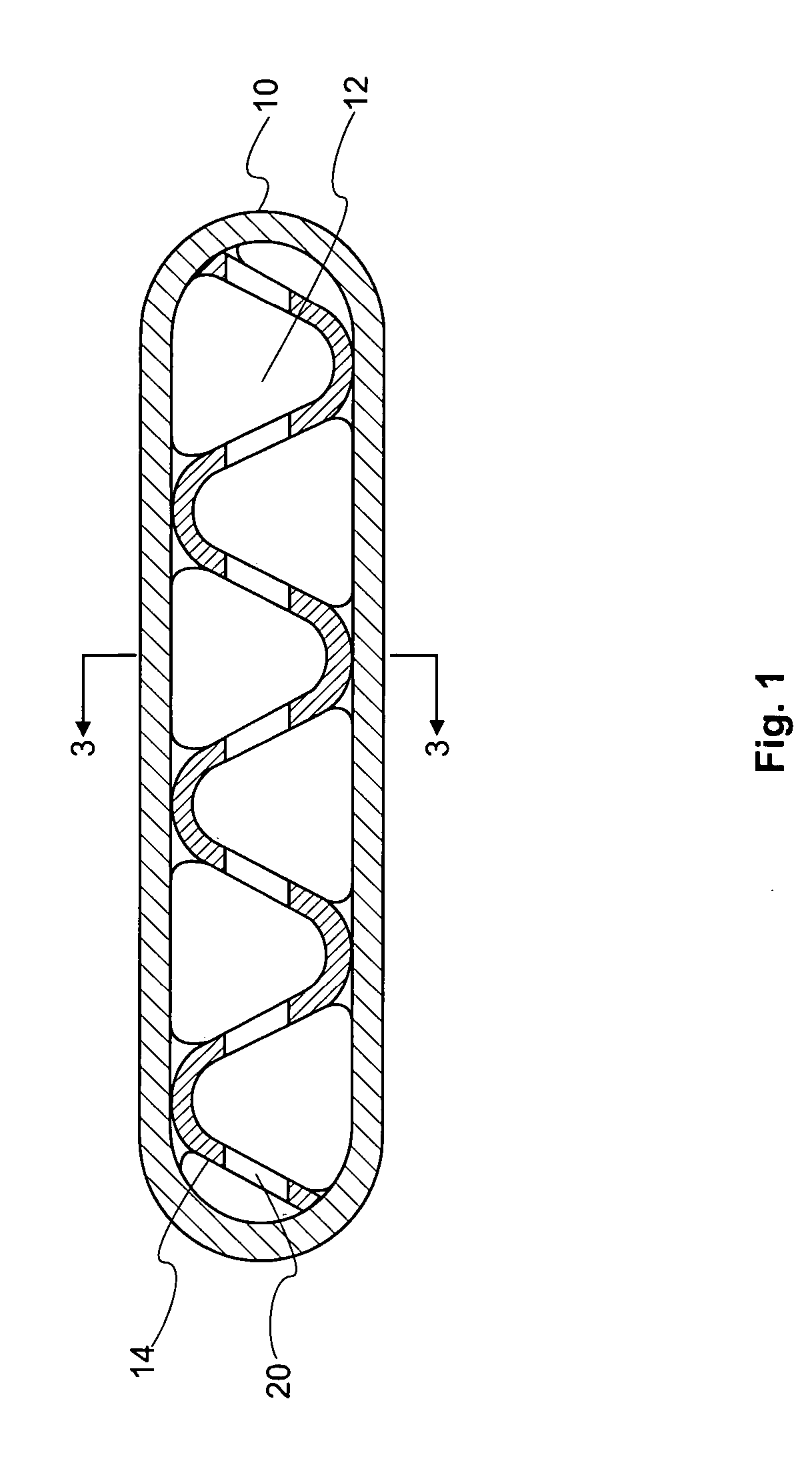
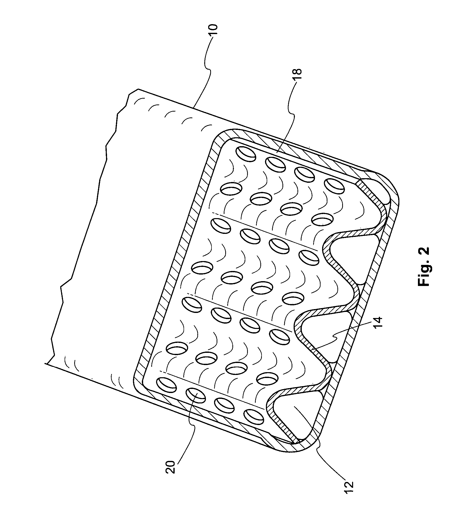
[0017] Referring to the drawings, the figures shows a heat exchange tube formed of a sheath 10 and microchannels 12 according to the present invention. The heat transfer tube is formed by a plurality of partitions 14 that form a plurality of microchannels 12. A heat transfer medium runs through the microchannels 12. In one embodiment, the invention includes at least about 2 to 12 partitions to form at least about 3 to 13 microchannels. In another preferred embodiment, at least about 4 to 8 partitions are present forming at least about 5 to 9 microchannels in the sheath.

[0018] The microchannels 12 define a path through which the heat transfer medium flows. As the heat transfer medium flows through a microchannel, it evaporates or condenses, thereby changing the vapor and liquid content of the composition. The microchannel at the front edge of the tube and the leeway edge of the tube may have different levels of heat transfer, due to external reasons. It is therefore possible that th...


PUM


Abstract

The invention relates to a microchannel tube for use in a heat transfer system. The microchannels have openings in the partitions that separate them from each other, thereby creating many short interconnected passages through which a heat transfer medium will flow in a laminar manner. This permits the liquid and vapor phases of the medium to mix, thereby increasing the efficiency of the system.

Description

CROSS-REFERENCE TO RELATED APPLICATION [0001] This application is a continuation-in-part of U.S. application Ser. No. 10 / 303,717, filed Nov. 26, 2002, the entire content of which is expressly incorporated herein by reference.FIELD OF INVENTION [0002] The present invention relates to an interconnected microchannel tube for use in a heat transfer device such as an automobile or residential or commercial air conditioning heat exchangers. The microchannel tubes are interconnected to facilitate re-mixing of the vapor-liquid phases and improve the efficiency of the heat exchanger. BACKGROUND OF THE INVENTION [0003] Microchannel tubes have been used in recent years in automotive air conditioning units and in residential or commercial air-conditioning heat exchangers. In use, a refrigerant flows through the multiple channels inside a float tube. The refrigerant evaporates and condenses as it passes through the tubes, absorbing and releasing heat as it changes phases between liquid and vapor...

Claims


Application Information

Patent Timeline
Patent Type & Authority Applications(United States)
IPC IPC(8): F28F1/00F28F3/02
CPCF28F1/003F28F2260/02F28F3/027
Inventor SHABTAY, YORAM LEONTANG, LIANGYOU
Owner OUTOKUMPU OY
Why Eureka
Try Eureka