
Hybrid multi-element tapered rotating tower

a technology of rotating tower and rotatable wind turbine, which is applied in the direction of wind energy generation, waterborne vessels, machines/engines, etc., can solve the problems of large structural components, corresponding increase in weight and material costs, and inability to provide aerodynamic or structurally efficient shapes, etc., to achieve the effect of enhancing energy production

Inactive Publication Date: 2011-02-22
ZUTECK MICHAEL D
View PDF18 Cites 17 Cited by
  • Summary
  • Abstract
  • Description
  • Claims
  • Application Information

AI Technical Summary

Benefits of technology

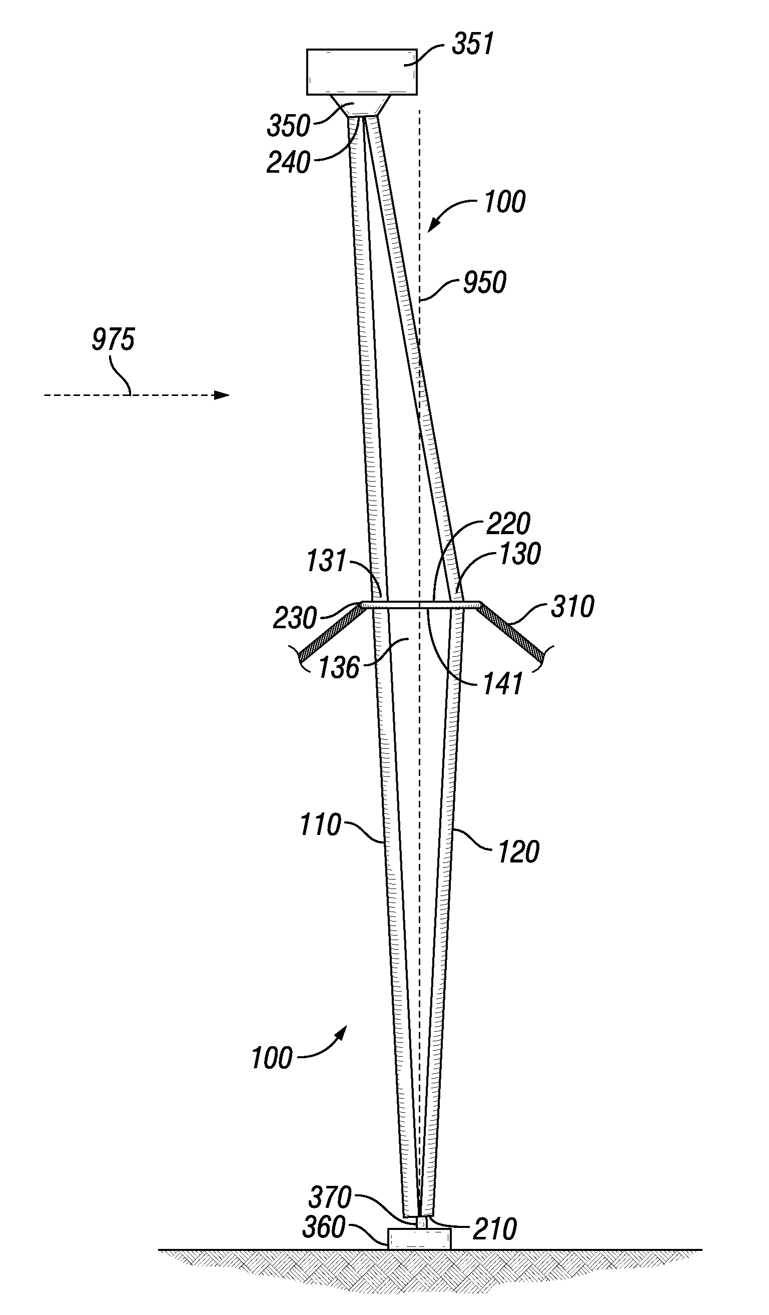
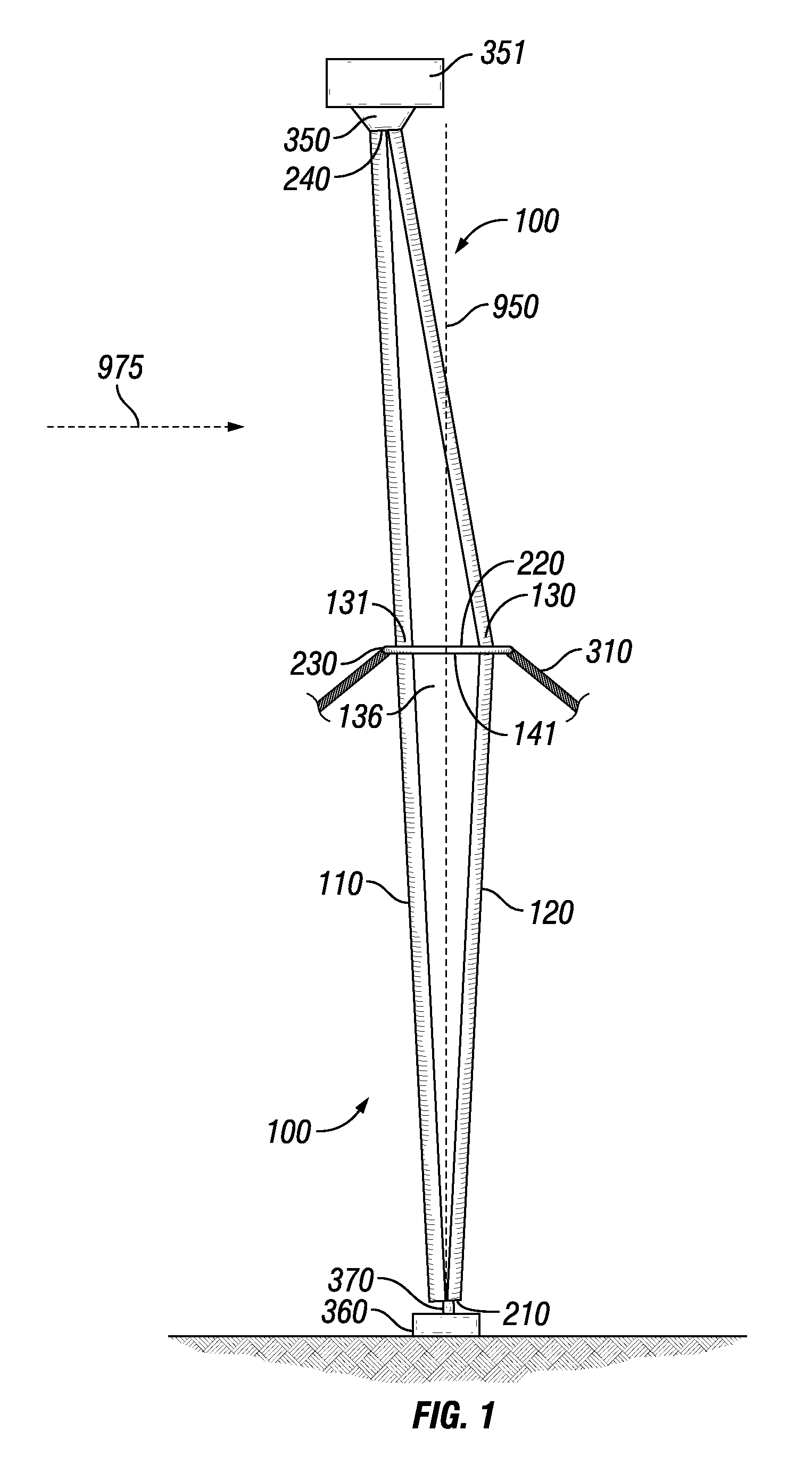
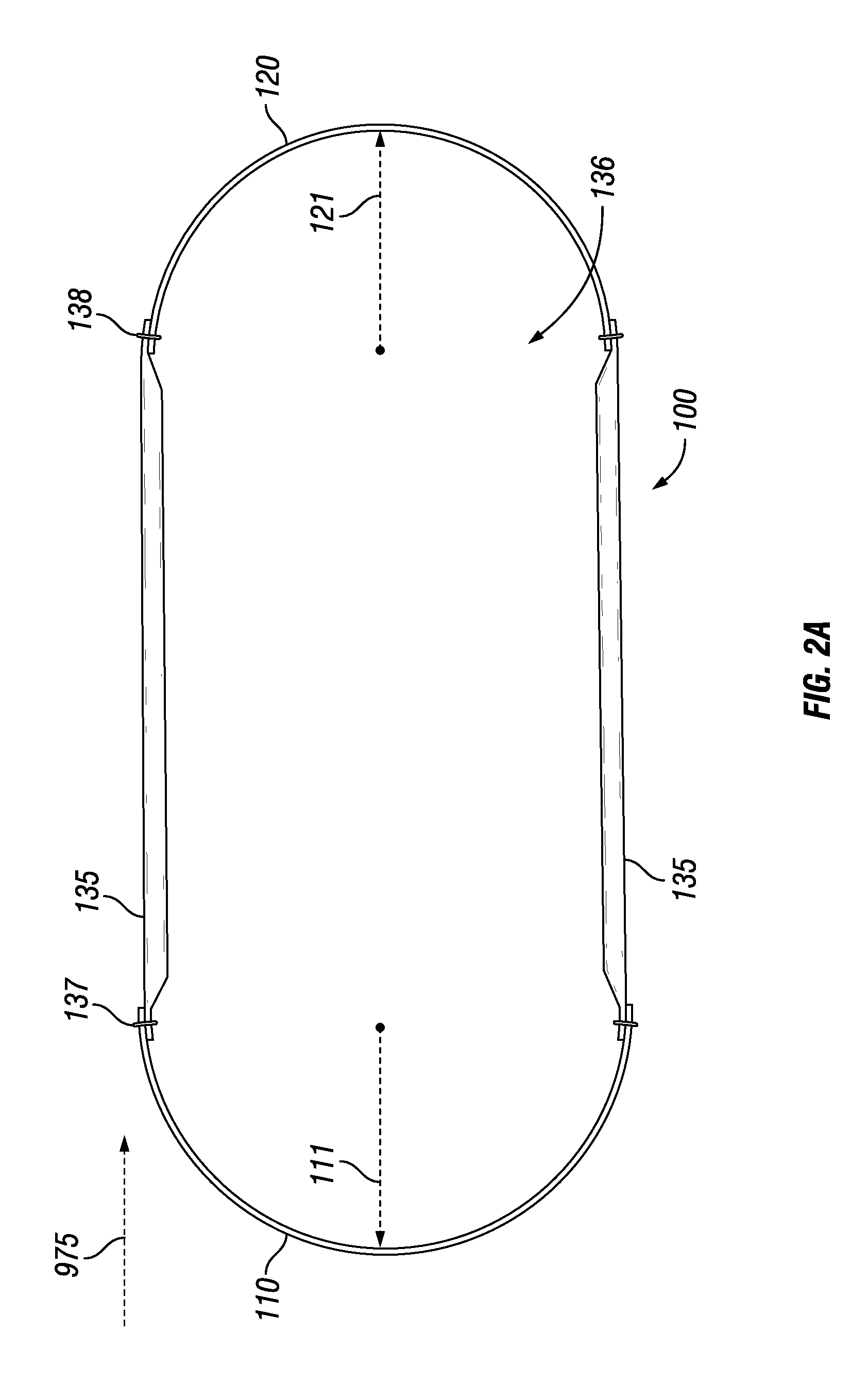
[0008]The tower structure may have a straight leading edge extending to the height of the structure. The narrow leading edge faces the wind direction and minimizes wind entry or passage drag and turbulence. The tower structure also contains a trailing edge similarly extending to the top of the structure. The trailing edge may bow outward expanding the width of the structure part way up the height of the structure. The trailing edge may taper toward the leading edge proximate to the tower ends. As used herein, the “upper tower segment” means that portion of the tower where the trailing edge tapers above the maximum outward bowing of the trailing edge to the leading edge. A triangular shaped structure discussed below merges the trailing edge into the leading edge proximate to the top of the tower.
[0013]The upper bearing assembly comprises an annular structure surrounding the wing shaped tower structure. Activation of the yaw motor and the rotation of the tower through operation of the lower and upper bearing assemblies causes the tower leading edge to continuously point into the wind. This in turn points the turbine, fixed to the top of the tower, into the wind thereby enhancing energy production.

Problems solved by technology

This goal encounters problems of transporting large structural components over land to the installation site.
It also encounters problems with materials required to withstand wind loads from all directions and the corresponding increase in weight and material costs.
Since the towers are fixed in place, it is not possible to provide an aerodynamic or structurally efficient shape since the wind direction is variable.

Method used


Image

  • Hybrid multi-element tapered rotating tower
  • Hybrid multi-element tapered rotating tower
  • Hybrid multi-element tapered rotating tower

Examples


Embodiment Construction

[0025]It will be appreciated that not all embodiments of the invention can be disclosed within the scope of this document and that additional embodiments of the invention will become apparent to persons skilled in the technology after reading this disclosure. These additional embodiments are claimed within the scope of this invention.

[0026]The contents of the section entitled Summary of Invention are incorporated into the Detailed Description of the Invention herein.

[0027]The construction of wind turbines and generation of electricity from these turbines has increased significantly in the last ten to twenty years. Most of these turbines utilize rotating blades and a nacelle containing a gear box and generator setting atop of a fixed positioned tower. The rotor and nacelle rotate atop of a stationary tower in response to changes in wind direction. This rotation may involve operation of a yaw motor.

[0028]There has been a goal to increase the size of the wind turbines. This goal encoun...


PUM


Abstract

The specification discloses a rotating turbine tower. The tower rotates to maintain the turbine facing into the wind. This allows structural optimization. The tower structure is comprised of a leading edge and a trailing edge, with joining panels between the edge structures. The tower edges are the main structural components of the tower. The separation of the edges tapers to follow the thrust bending moment on the tower, reducing the need to taper material thickness. The tapering shape of the tower structure matches the primary edgewise moment distribution. The tower can be assembled on site from components, thereby facilitating transportation to the tower site. The material properties and shape can be selected based upon the tower maintaining a near constant orientation with the wind. This can save weight and costs. The tower architecture can be of differing shapes such as a triangle or a structure tapering at each end.

Description

RELATED APPLICATION[0001]This application is a continuation in part of application Ser. No. 12 / 554,884, entitled “Hybrid Multi-element Tapered Rotating Tower” filed Sep. 5, 2009 which is incorporated by reference in its entirety.BACKGROUND TO INVENTION[0002]1. Intended Use[0003]The invention is an advantageous construction of a rotatable wind turbine tower. The turbine includes the rotor and nacelle. The turbine is attached at the top of the tower and changes direction with the rotation of the tower. The tower has a narrow profile in one dimension and a broad profile in a second dimension. This shape, combined with bearings, allows the tower to change orientation in response to changes in wind direction, aligning the structure with the wind direction to optimally carry the loads, and thereby reducing the weight and cost of the tower.[0004]2. Related Technology[0005]Wind powered turbines are known. Most of these turbines utilize a stationary tower and the turbine rotates 360° in a ho...

Claims


Application Information

Patent Timeline
IPC IPC(8): F03D7/02
CPCF03D1/04F03D1/00F03D7/0204F03D80/00F03D80/70F03D13/20F03D7/02Y10S415/908F05B2240/12F05B2240/912F05B2250/411F05B2250/70Y02E10/723Y02E10/728F05B2240/54Y02E10/72
Inventor ZUTECK, MICHAEL D.
Owner ZUTECK MICHAEL D
Learn More