Method of driving a gas-discharge lamp

a technology of gas-discharge lamps and drivers, which is applied in the direction of gas-filled discharge tubes, electric discharge lamps, non-electron-emitting electrodes, etc., can solve the problems of reducing the lifetime of the driver (and therefore the lifetime of the lamp itself), affecting the efficiency of the lamp, and reducing the power of the lamp. , to achieve the effect of reducing the effect of power consumption, reducing the effect of efficacy and maintaining the effect of the lamp

Inactive Publication Date: 2015-10-13
LUMILEDS
View PDF16 Cites 0 Cited by
  • Summary
  • Abstract
  • Description
  • Claims
  • Application Information

AI Technical Summary

Benefits of technology

[0015]With the method according to the invention, the choice of anode ensures that the temperature at the coldest spot can be intentionally and deliberately raised during DC operation so that a condensation of the metal salts is largely prevented, leaving these metal salts available in the gas phase. As a direct result, the efficacy of the lamp is maintained at a favourably high level. In contrast to a prior art method in which the anode function is not allocated to a specific electrode in consideration of a coldest spot asymmetry, resulting in a significant drop in efficacy during a DC mode of operation, the method according to the invention ensures that the lamp efficacy in a DC mode of operation is comparable to that obtainable during an AC mode of operation.
[0039]To track the development of the environment variable during operation of the lamp, the gas-discharge lamp according to the invention preferably comprises a suitable monitoring unit for monitoring the environment variable, which monitoring unit is realised to provide the lamp driver with an environment variable value. This monitoring unit can be located at any suitable position, preferably such that it can monitor the variable in a critical region such as a socket region. Preferably, the monitoring unit comprises a temperature sensor, since a direct measurement of the temperature can provide a reliable report of the situation in the critical region, and the driver can react accordingly. Of course, such a monitoring unit could also be incorporated in the driver. Other monitoring means are conceivable. For example, an infrared sensor could be used to monitor the temperature development in the lamp and to determine the location of the coldest spot. In another embodiment, a pair of sensors could be used to monitor a temperature gradient across the lamp, for example by measuring the temperature at each end of the lamp or at each electrode.

Problems solved by technology

However, under certain circumstances, the temperature in the housing of the lamp may reach extreme levels, and the components of the driver, particularly temperature-sensitive semiconductor components, may not be able to withstand these temperatures.
As a result, one or more driver components may become damaged and may even fail, so that the lifetime of the driver (and therefore the lifetime of the lamp itself) is significantly shortened.
Such a compact design also cannot accommodate a large heat-sink.
However, reducing the lamp power, i.e. ‘dimming’ the lamp, has the direct consequence of lowering the temperature in the coldest spot of the discharge vessel.
When the coldest spot temperature is lowered, the metal salts of the fill can partially condense and are subsequently unavailable in the gas phase, reducing the efficacy of the lamp, wherein efficacy is expressed as a ratio of the luminous flux to the power required to produce that luminous flux, i.e. lumens per Watt.
The result is a noticeable drop in light output.
When the lamp power of an AC-driven lamp is reduced to approach a certain minimum, the commutation behaviour of the lamp can start to exhibit unfavourable behaviour.
For example, at a zero-crossing of the lamp current, this may remain at or close to zero for a significant duration, so that the discharge arc becomes unstable.
If the lamp power is held at this minimum for too long, the discharge arc will most likely eventually extinguish.

Method used


Image

  • Method of driving a gas-discharge lamp
  • Method of driving a gas-discharge lamp
  • Method of driving a gas-discharge lamp

Examples


Embodiment Construction

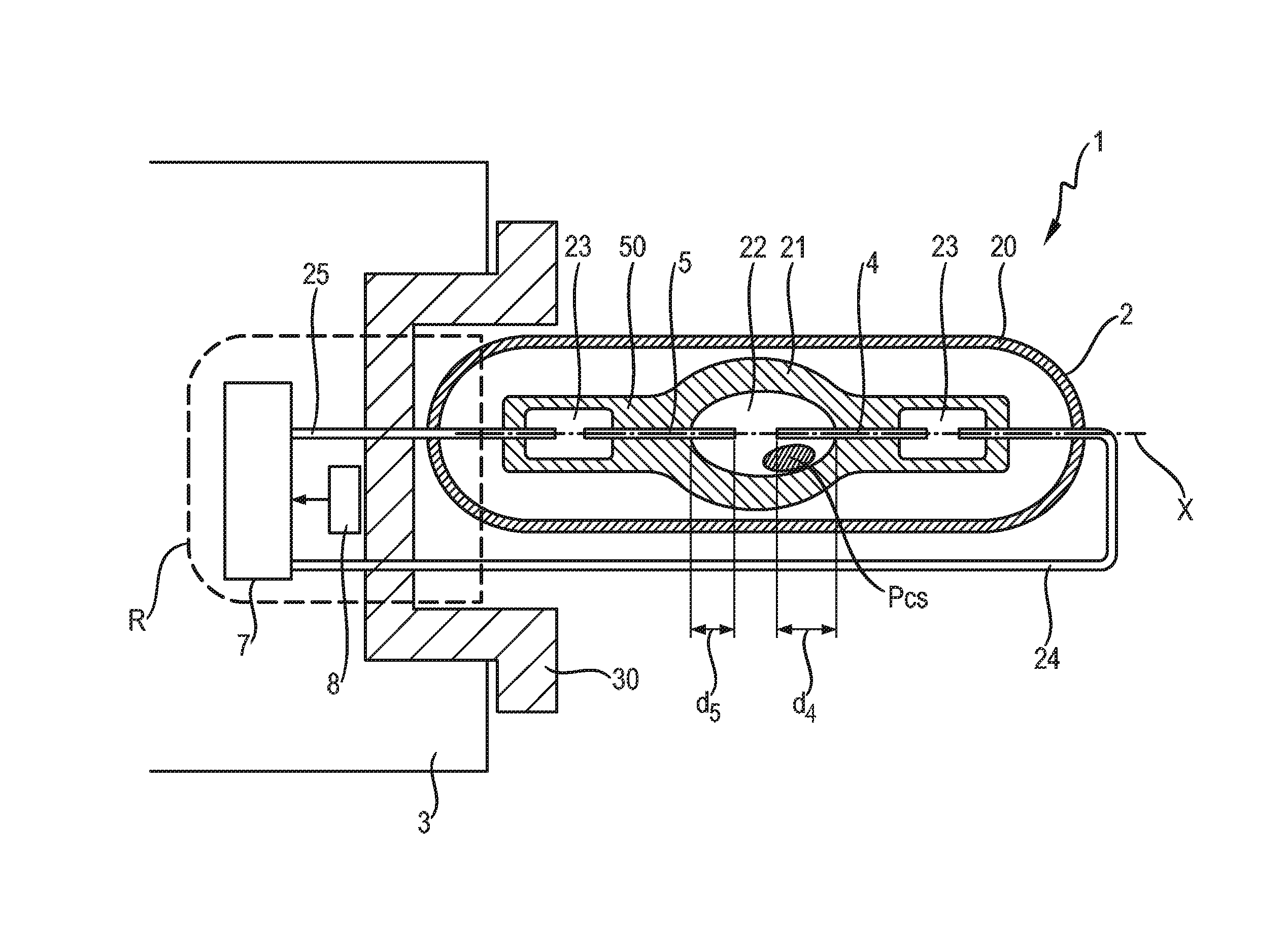
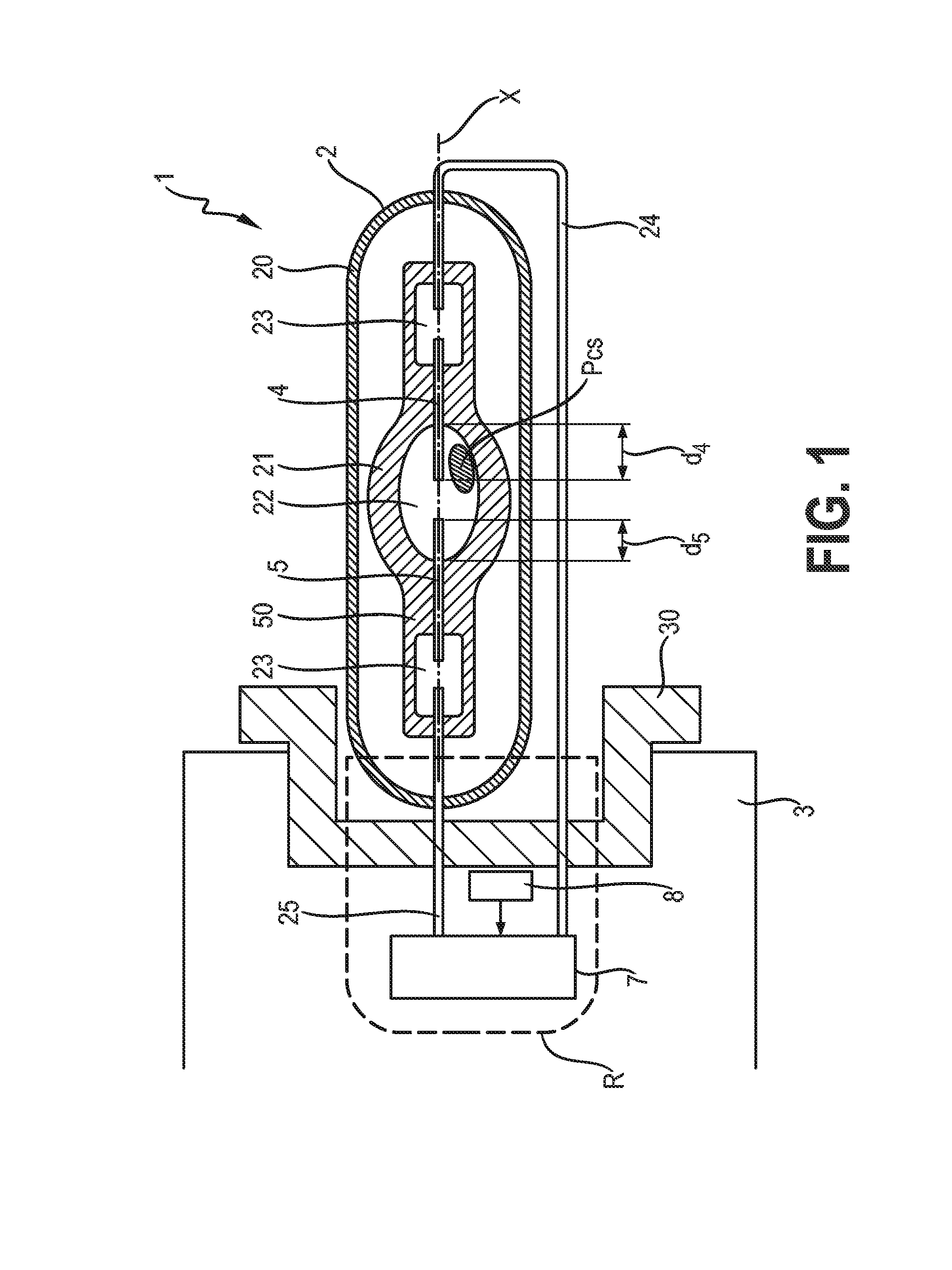
[0048]FIG. 1 shows a gas-discharge lamp 1 according to an embodiment of the invention. The lamp 1 comprises a burner 2 mounted in a base 3. In an automotive front lighting arrangement, such a lamp 1 is generally mounted horizontally in a housing so that the longitudinal axis X of the burner 2 is essentially horizontal. The burner 2 comprises an outer glass vessel 20 enclosing an inner discharge vessel 21. The discharge vessel 21, usually a quartz glass bulb 21, comprises a pair of electrodes 4, 5 arranged along the optical axis X to face each other across a short gap in a discharge chamber 22, which is sealed by two pinches 40, 50. The exposed length d4 of the outer electrode 4 is slightly longer than the exposed length d5 of the inner electrode 5. This can be the result of a deliberate ‘shifting’ of the electrodes along the longitudinal axis of the burner to offset the gap that separates the front faces of the electrodes towards the base of the lamp. Alternatively, the longer expos...


PUM


Abstract

The invention describes a method of driving a gas-discharge lamp (1) according to conditions in a specific region (R) of the lamp (1), which gas-discharge lamp (1) comprises a burner (2) in which a first electrode (4) and a second electrode (5) are arranged on either side of a discharge gap, which lamp (1) is realised such that the position (PCs) of a coldest spot during an AC mode of operation is in the vicinity of the first electrode (4), which method comprises the steps of initially driving the lamp (1) in the AC mode of operation; monitoring an environment variable of the lamp (1), which environment variable is indicative of conditions in a specific region (R) of the lamp (1); switching to a temporary DC mode of operation at a DC power value on the basis of the monitored environment variable, whereby the first electrode (4) is allocated as the anode; and driving the lamp (1) in the DC mode of operation until the monitored environment variable has returned to an intermediate environment variable threshold value (TDCAC). The invention also describes a gas-discharge lamp and a driver for a gas-discharge lamp.

Description

CROSS-REFERENCE TO PRIOR APPLICATIONS[0001]This application is the U.S. National Phase application under 35 U.S.C. §371 of International Application No. PCT / IB2012 / 051020, filed on Mar. 5, 2012, which claims the benefit of European Patent Application No. 11157595.7, filed on Mar. 10, 2011. These applications are hereby incorporated by reference herein.FIELD OF THE INVENTION[0002]The invention describes a method of driving a gas-discharge lamp, a gas-discharge lamp, and a driver of a gas-discharge lamp.BACKGROUND OF THE INVENTION[0003]Gas-discharge lamps are often used in lighting applications requiring a very bright light source. One example is a front lighting application, such as in a front headlight of a vehicle. Another example might be the illumination of an interior space such as an underground tunnel. A gas-discharge lamp for such applications is generally driven using AC (alternating current). In a front headlight application using a gas-discharge lamp as light source, a lig...

Claims


Application Information

Patent Timeline
Patent Type & Authority Patents(United States)
IPC IPC(8): H01J7/24H01J19/36H05B41/36H05B41/292H05B41/38
CPCH05B41/36H05B41/38H05B41/2926
Inventor HAACKE, MICHAELDABRINGHAUSEN, LARSRIEDERER, XAVERHUEDEPOHL, HEINZ HELMUT
Owner LUMILEDS
Why Eureka
Try Eureka