Three-dimensional profilometer
a three-dimensional, profilometer technology, applied in the field of industrial metrology, can solve problems such as time-consuming processes
Active Publication Date: 2015-10-20
INTELLISENSE SYST INC
View PDF14 Cites 21 Cited by
- Summary
- Abstract
- Description
- Claims
- Application Information
AI Technical Summary
Benefits of technology
The patent describes technology that uses a laser or digital micromirror device to create a line on a surface and scan it to create a three-dimensional point cloud to determine the profile of the surface. This technology can be used in industrial metrology and other applications. Different embodiments of the technology may use multiple lines or patterns for more precise measurements. The summary is not meant to limit the scope of any inventions described herein, which are defined solely by the claims attached to this patent.
Problems solved by technology
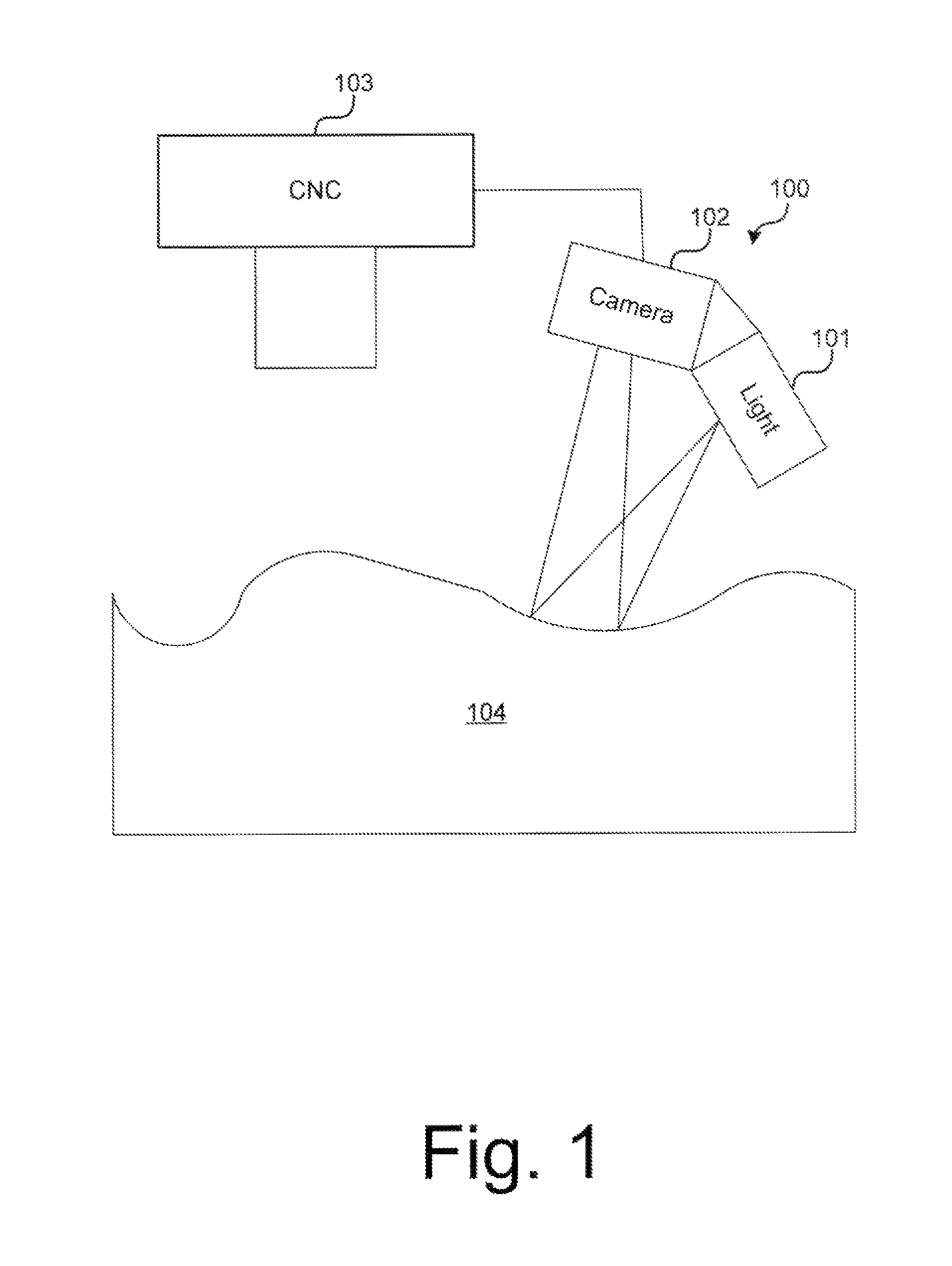
This process is time consuming because the touch probe needs to touch several spots on each feature to record the precise location and key characteristics of each machined feature, requiring the CNC machine head to be driven precisely to each location for each touch on the part.
Method used
View moreImage
Smart ImageViewing Examples
Examples
second embodiment
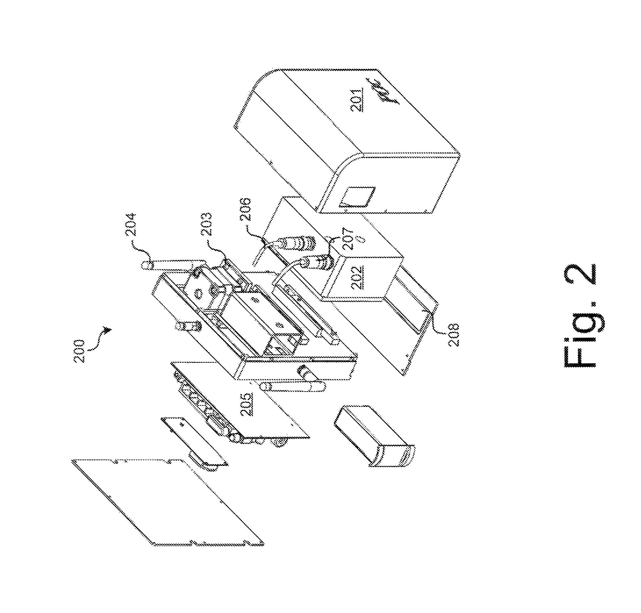
[0009]FIG. 2 illustrates a line scanning 3D profilometer in accordance with the technology described herein.
third embodiment
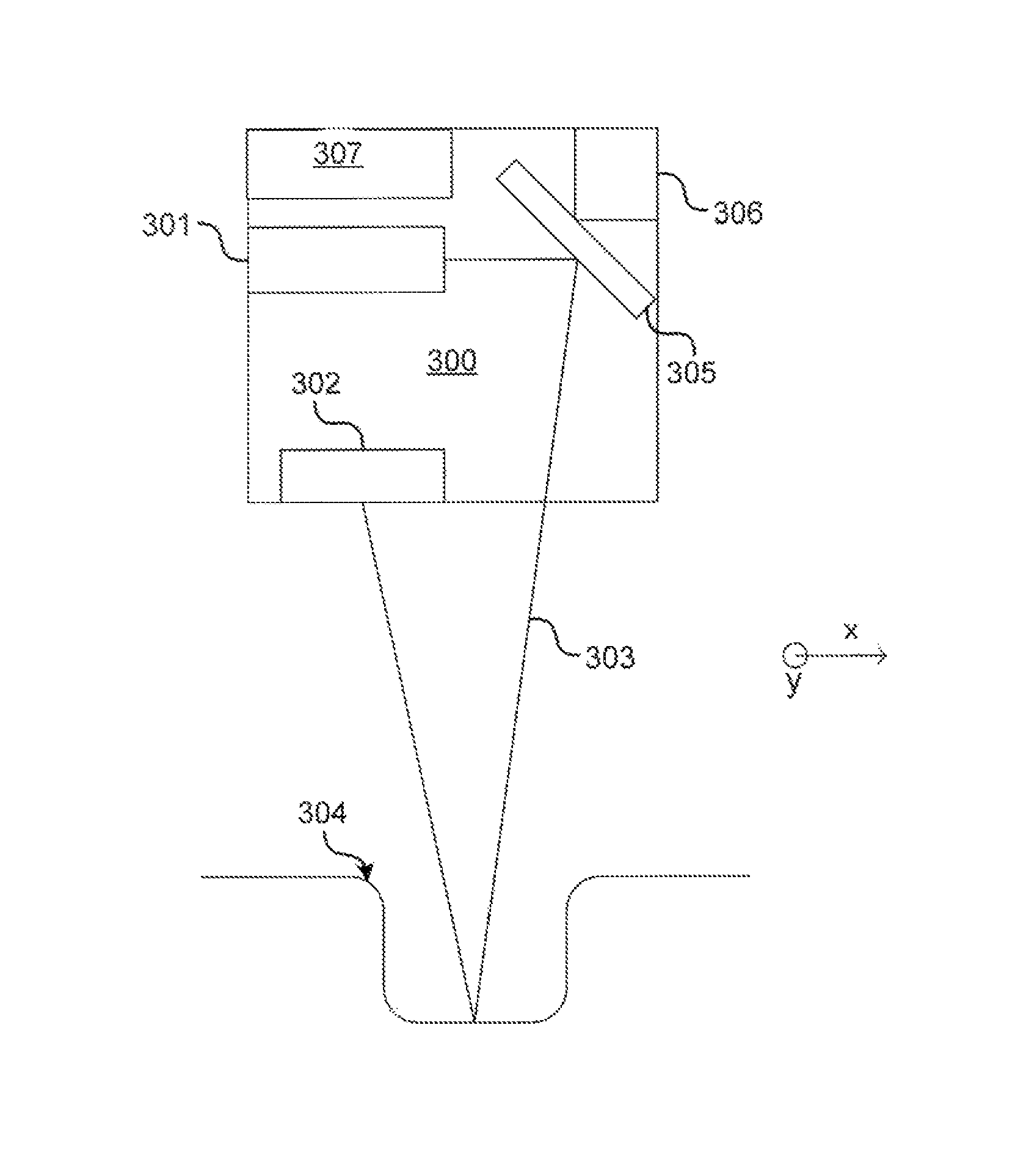
[0010]FIG. 3 illustrates a line scanning 3D profilometer in accordance with the technology described herein.
fourth embodiment
[0011]FIG. 4 illustrates a line scanning 3D profilometer in accordance with the technology described herein.
Login to View More PUM
 Abstract
Profilometers for industrial metrology and other applications are described. A line is projected on a surface to be profiled. The line is scanned to build a three dimensional point cloud allowing the three-dimensional (3D) profile of the surface to be determined. In some embodiments, the line is projected by a laser system. In other embodiments, the line is projected by a digital micromirror device (DMD). In still further embodiments, multiple lines, or other patterns are projected.
Description
CROSS-REFERENCE TO RELATED APPLICATIONS[0001]This application claims the benefit of: U.S. Provisional Application No. 61 / 643,796, filed May 7, 2012; U.S. Provisional Application No. 61 / 664,616, filed Jun. 26, 2012; and U.S. Provisional Application No. 61 / 702,130, filed Sep. 17, 2012, and which are hereby incorporated herein by reference in their entireties.STATEMENT OF RIGHTS TO INVENTIONS MADE UNDER FEDERALLY SPONSORED RESEARCH[0002]This invention was made with Government support under Contract No. FA8650-11-M-5196 awarded by the Air Force Research Laboratory. The Government has certain rights in the invention.TECHNICAL FIELD[0003]The disclosed technology relates generally to industrial metrology, and more particularly, some embodiments relate to systems and methods for scanning three-dimensional (3D) profilometry.DESCRIPTION OF THE RELATED ART[0004]In the general area of industrial metrology, ouch probes are used in precision milling or drilling machines (PMMs), coordinate measure...
Claims
Login to View More Application Information
Patent Timeline
 IPC IPC(8): G01B11/24
CPCG01B11/24G01B11/25G01B11/2513
Inventor ULMER, CHRISTOPHER THADSHNITSER, PAULMILLER, DAVID HAROLDPATTON, EDWARD MATTHEWWILKINSON, PAUL
Owner INTELLISENSE SYST INC
Features
- R&D
- Intellectual Property
- Life Sciences
- Materials
- Tech Scout
- Unparalleled Data Quality
- Higher Quality Content
- 60% Fewer Hallucinations
Learn More Browse by: Latest US Patents, China's latest patents, Technical Efficacy Thesaurus, Application Domain, Technology Topic, Popular Technical Reports.
© 2025 PatSnap. All rights reserved.Legal|Privacy policy|Modern Slavery Act Transparency Statement|Sitemap|About US| Contact US: help@patsnap.com


