Liquid crystal display device

a liquid crystal display and backlight technology, applied in non-linear optics, instruments, optics, etc., can solve the problems that the backlight and the liquid crystal display panel cannot be fixed to and integrated with each other

Active Publication Date: 2015-10-20
JAPAN DISPLAY INC
View PDF4 Cites 3 Cited by
  • Summary
  • Abstract
  • Description
  • Claims
  • Application Information

AI Technical Summary

Problems solved by technology

However, when the picture-frame of the liquid crystal display panel is narrowed, an area for attaching the double-faced tape is not secured in the liquid crystal display panel, leading to a problem that the backlight and the liquid crystal display panel cannot be fixed to and integrated with each other.

Method used


Image

  • Liquid crystal display device
  • Liquid crystal display device
  • Liquid crystal display device

Examples


Embodiment Construction

[0030]Hereinafter, an embodiment of the invention will be described with reference to the drawings.

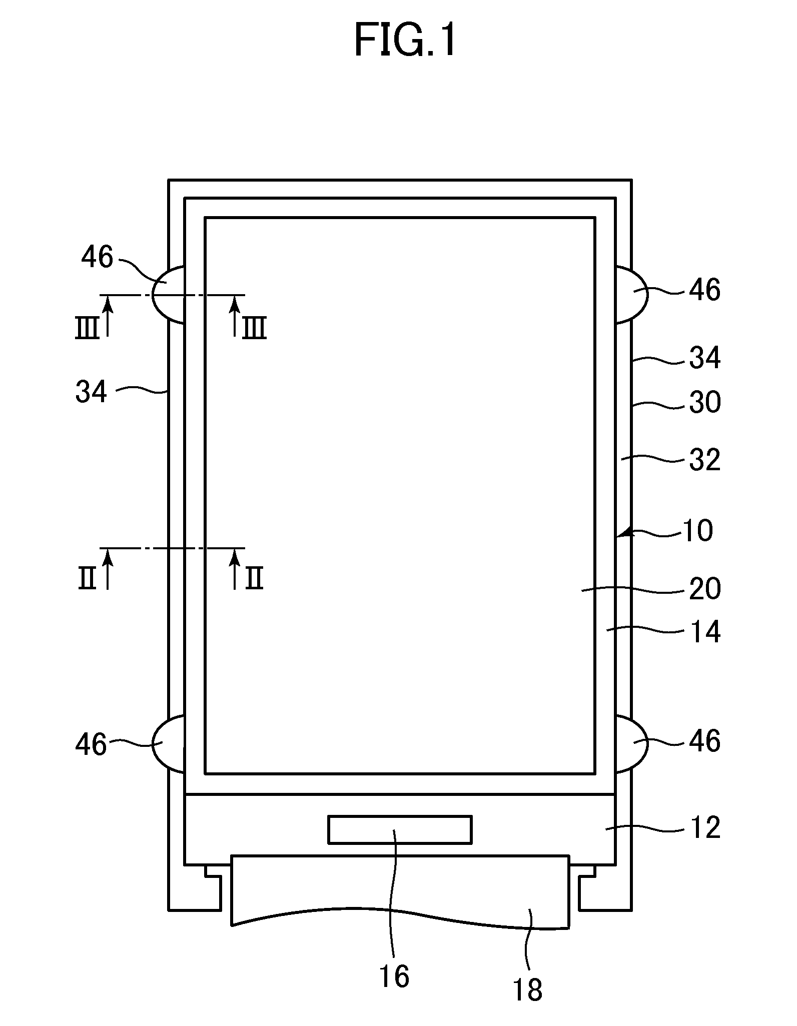
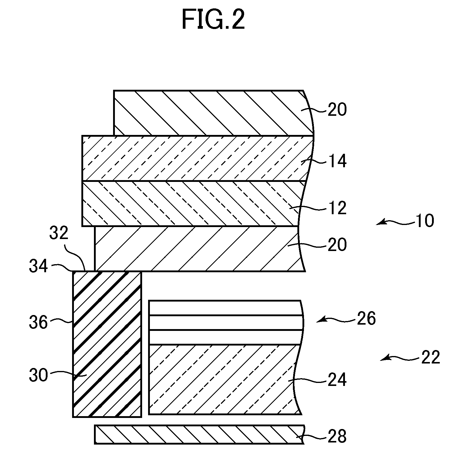
[0031]FIG. 1 is a plan view showing a liquid crystal display device according to the embodiment of the invention. FIG. 2 is a cross-sectional view of the liquid crystal display device shown in FIG. 1, taken along line II-II.

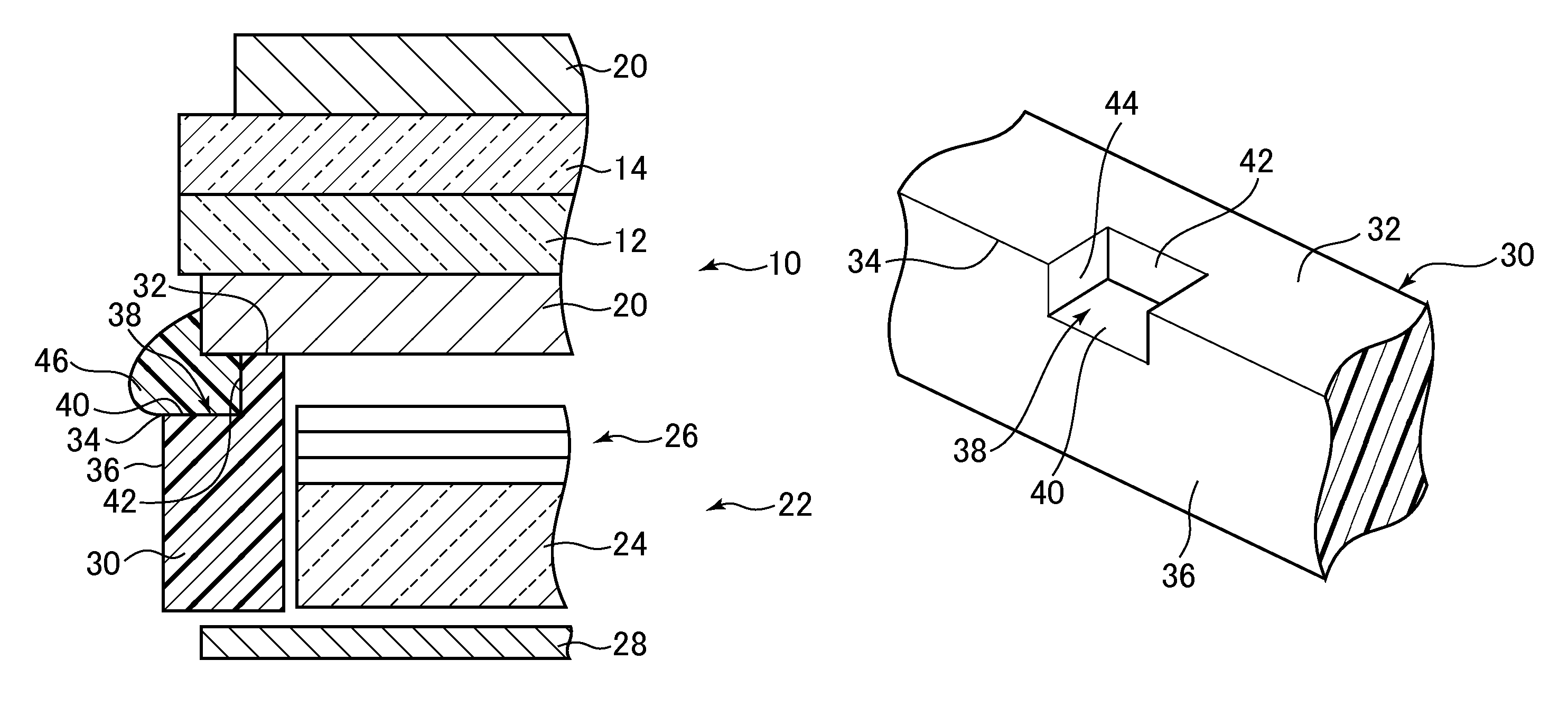
[0032]The liquid crystal display device includes a liquid crystal display panel 10. The liquid crystal display panel 10 includes a pair of substrates 12 and 14 (both of which are glass substrates, for example) between which liquid crystal (not shown) is present. The substrate 12 is a TFT (Thin Film Transistor) substrate (or an array substrate) including thin film transistors, pixel electrodes, and wires (all of which are not shown), while the substrate 14 is a color filter substrate on which color filters (not shown) are formed. The substrate 12 includes a protruding portion protruding from the substrate 14. On the liquid crystal display panel 10 (specifically the p...


PUM

PropertyMeasurementUnit
sizeaaaaaaaaaa
widthaaaaaaaaaa
reflectionaaaaaaaaaa

Abstract

A liquid crystal display device includes a liquid crystal display panel and a backlight. The backlight includes a light guide plate arranged so as to overlap the liquid crystal display panel, an optical sheet arranged between the liquid crystal display panel and the light guide plate, a frame accommodating the light guide plate therein and facing a circumferential edge portion of the liquid crystal display panel, and an adhesive fixing the circumferential edge portion of the liquid crystal display panel to the frame. The frame includes a recess penetrating an outer side surface and an upper surface facing the circumferential edge portion of the liquid crystal display panel. The adhesive is arranged in the recess.

Description

CROSS-REFERENCE TO RELATED APPLICATION[0001]The present application claims priority from Japanese application JP2012-280907 filed on Dec. 25, 2012, the content of which is hereby incorporated by reference into this application.BACKGROUND OF THE INVENTION[0002]1. Field of the Invention[0003]The present invention relates to a liquid crystal display device.[0004]2. Description of the Related Art[0005]A backlight of a liquid crystal display device includes a light guide plate for converting a point light source to a surface light source. A plurality of light-emitting components are arranged in a line so as to face an edge surface of the light guide plate (JP 2010-62016 A). Light emitted from the light-emitting component as a point light source is incident on the edge surface of the light guide plate, and emitted by reflection from a surface of the light guide plate to a liquid crystal display panel. The light-emitting components and the light guide plate are accommodated in a frame. Suc...

Claims


Application Information

Patent Timeline
Patent Type & Authority Patents(United States)
IPC IPC(8): G02F1/1335G02F1/1333
CPCG02F1/133615G02F1/133308G02F2001/133314G02F2202/28G02F1/133314
Inventor MATSUMOTO, SHOHEIOOHIRA, EIJI
Owner JAPAN DISPLAY INC
Why Eureka
Try Eureka