
Simplified device of a camera unit of a motor vehicle

a camera unit and motor vehicle technology, applied in the field of simplified devices, can solve the problems of high installation space requirements, inflexible arrangement, and vulnerable cameras, and achieve the effects of simple and inexpensive devices, effective protection of camera units, and simple and inexpensive devices

Active Publication Date: 2015-10-20
HUF HULSBECK & FURST GMBH & CO KG
View PDF26 Cites 2 Cited by
  • Summary
  • Abstract
  • Description
  • Claims
  • Application Information

AI Technical Summary

Benefits of technology

[0006]Therefore, the invention provides a simple and inexpensive device for a motor vehicle with a camera unit that avoids the aforementioned drawbacks. In particular, the device shall have few components, shall have a compact design and shall provide effective protection for the camera unit, especially in the retracted state. Furthermore, a vehicle with a simple and inexpensive device with a camera unit shall be provided.

Problems solved by technology

Such a camera arrangement is inflexible, has a very high installation space requirement and protects the camera in the retracted state only under certain conditions, because the lens of the camera is aimed at an oblique angle relative to the opening or more specifically relative to the cover.
Such a camera arrangement makes the camera vulnerable even in the closed state.
It has been found that the drawback with such a device is that the direct arrangement of the camera at the protective element is susceptible to trouble.
Due to the effects of weather and wear phenomena, the protective element no longer forms a satisfactory seal after a certain period of time, so that the camera unit, fastened to the protective element, is exposed to certain adverse effects of dirt and moisture.
Therefore, in particular, the lenses of the video camera have to be cleaned frequently.
Furthermore, owing to the direct arrangement of the camera at the protective element, the camera can be easily damaged by jolting or bumping the protective element.
The drawback with this device is that the motor has a first mechanism for moving the camera unit and a second mechanism for moving the protective element.
This arrangement makes the design of the device more complicated.
That is, the device requires a relatively large number of components, so that the manufacture of such a device is also cost intensive.

Method used


Image

  • Simplified device of a camera unit of a motor vehicle
  • Simplified device of a camera unit of a motor vehicle
  • Simplified device of a camera unit of a motor vehicle

Examples


Embodiment Construction

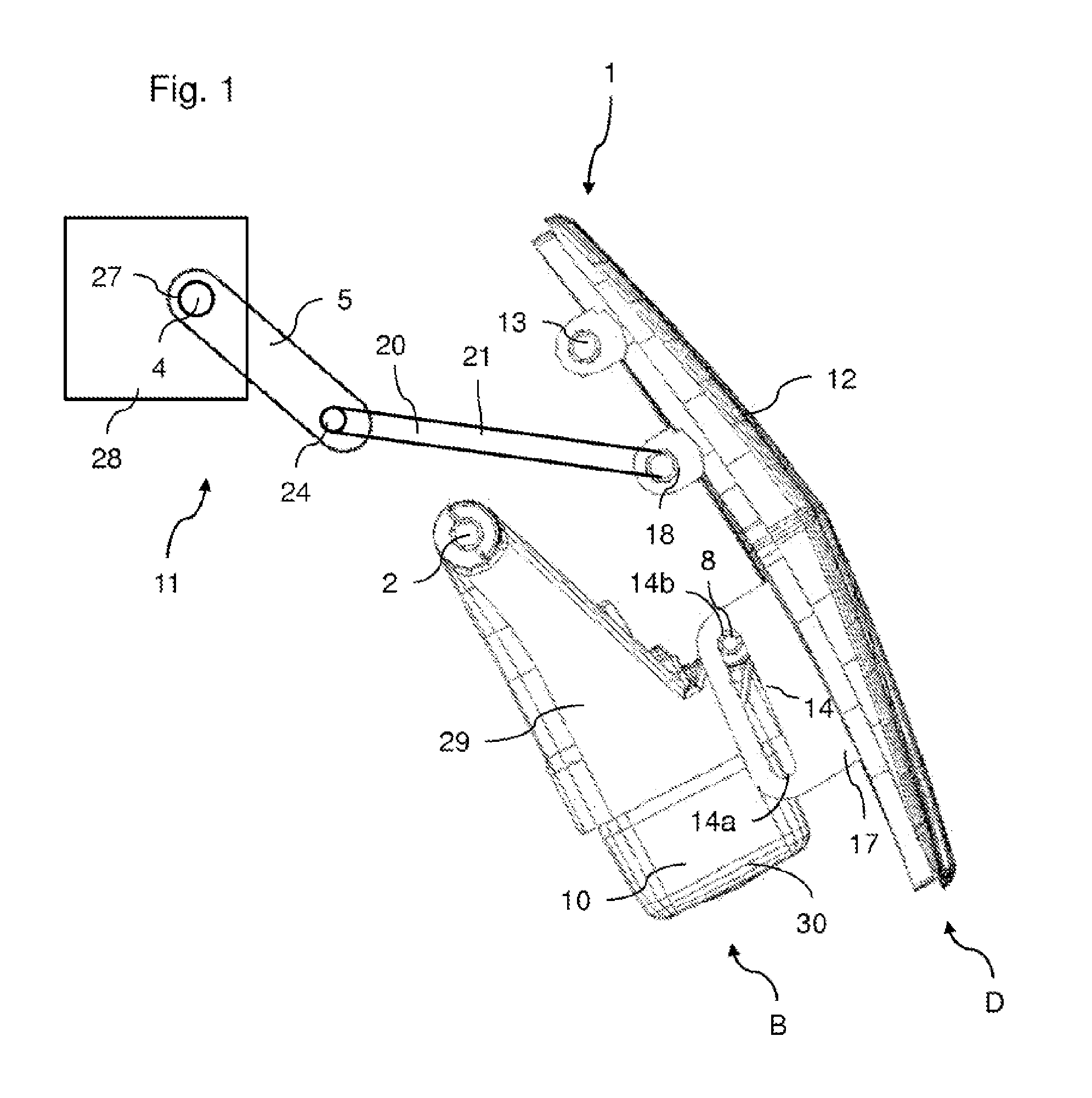
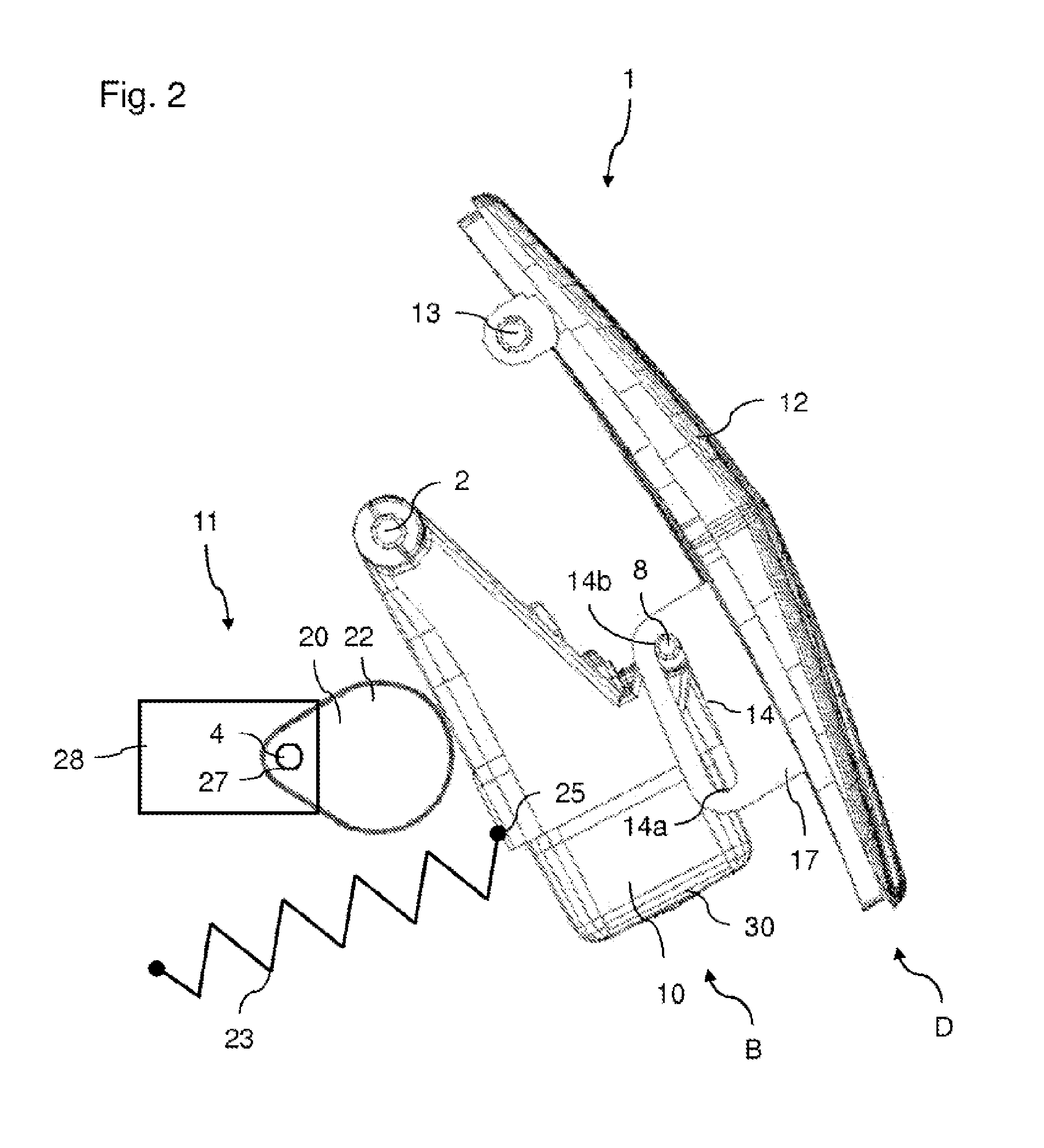
[0054]Elements having an identical function and operating mode are provided with the same reference numerals and symbols in the FIGS. 1 to 8.

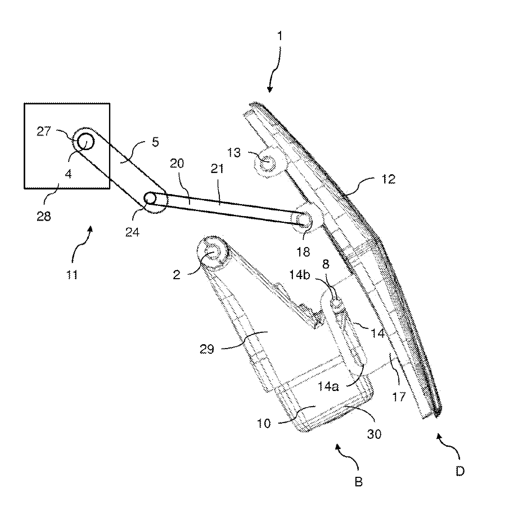
[0055]FIG. 1 is a side view of a first possible design variant of the device 1 that is intended for a motor vehicle and that comprises a camera unit 10, in particular a movably mounted camera unit 10, which is configured according to the design principle of the invention. The device 1 is characterized by the fact that the camera unit 10 and the protective element 12 are movably hinged together. As a result of this feature, the camera unit 10 follows the protective element 12, when said protective element is moved by means of the drive unit 11. The protective element 12 is mounted rotatably and / or pivotably about a first axle 13. The first axle 13 is securely arranged at the device 1 or at the motor vehicle, at which the device 1 is arranged. The camera unit 10 is mounted rotatably about a second axle 2. The camera unit 10 of the device can have...


PUM


Abstract

A device for a motor vehicle has a camera unit, which can be brought into an inactive position and an active position includes a protective element, which can be guided into a closed position and an open position. In the closed position, the camera unit is in its inactive position behind the protective element, where it is inaccessible from the outside. In the open position, the camera unit is in its active position for image acquisition. The device further includes a drive unit for moving the camera unit and the protective element, wherein the camera unit and protective element are movably hinged to each other. A vehicle, particularly a motor vehicle, could be equipped with such a device.

Description

TECHNICAL FIELD[0001]The invention relates to a device that is intended for a motor vehicle and that has a camera unit, which can be brought into an inactive position and into an active position, and has a protective element, which can be guided into a closed position and into an open position, so that in the closed position of the protective element the camera unit is in its inactive position behind the protective element, where it is inaccessible from the outside, and in the open position of the protective element the camera unit is in its active position for image acquisition, and the device has a drive unit for moving the camera unit and the protective element. Furthermore, the invention relates to a motor vehicle with a camera unit.BRIEF DESCRIPTION OF RELATED ART[0002]The use of cameras or more specifically a camera unit for detecting the surrounding area of a vehicle is known from the prior art. Such camera units are used, for example, as parking aids and / or maneuvering aids ...

Claims


Application Information

Patent Timeline
Patent Type & Authority Patents(United States)
IPC IPC(8): G03B17/00B60R11/04H04N5/225B60R11/00
CPCH04N5/2254B60R11/04B60R2011/0082B60R2011/0085B60R2011/0092B60R2011/0094H04N23/57
Inventor SCHUTZ, HEIKO
Owner HUF HULSBECK & FURST GMBH & CO KG
Learn More