Instrument for rapid measurement of the optical properties of the eye in the entire field of vision

a technology of optical properties and instruments, applied in the field of optical properties, can solve the problems of poor angular resolution, eye changes in aberrations, and requires a large amount of tim

Active Publication Date: 2015-10-27
UNIVERSITY OF MURCIA
View PDF30 Cites 4 Cited by
  • Summary
  • Abstract
  • Description
  • Claims
  • Application Information

AI Technical Summary

Benefits of technology

[0028]Another advantage of the invention is that the subject whose eye is going to be measured remains still, without having to change his line of sight.
[0029]Another advantage of the invention is that it enables the subject whose eye is going to be measured to remain stationary and comfortable, as it is possible to equip the instrument with a chin rest to support the chin.
[0030]Other features and advantages of the present invention will be disclosed in the detailed description that follows from an exemplary embodiment of its object in relation to the accompanying figures.

Problems solved by technology

The measurements require a good deal of time (several minutes) and in order to shorten the time, the number of angles is reduced, which results in poor angular resolution.
Furthermore, there are questions about whether rotating the eye changes the aberrations due to the tension of the eye muscles on the optics of the eye.
Moreover, due to its design, a mirror moves in front of the subject, a situation that could give rise to errors when used on subjects who lack experience, as they will tend to follow it during the measurement.
The drawbacks are that the measurements have a very low density, as only a 30° field can be measured, which is too little to form a good idea of the peripheral vision.

Method used


Image

  • Instrument for rapid measurement of the optical properties of the eye in the entire field of vision
  • Instrument for rapid measurement of the optical properties of the eye in the entire field of vision
  • Instrument for rapid measurement of the optical properties of the eye in the entire field of vision

Examples


Embodiment Construction

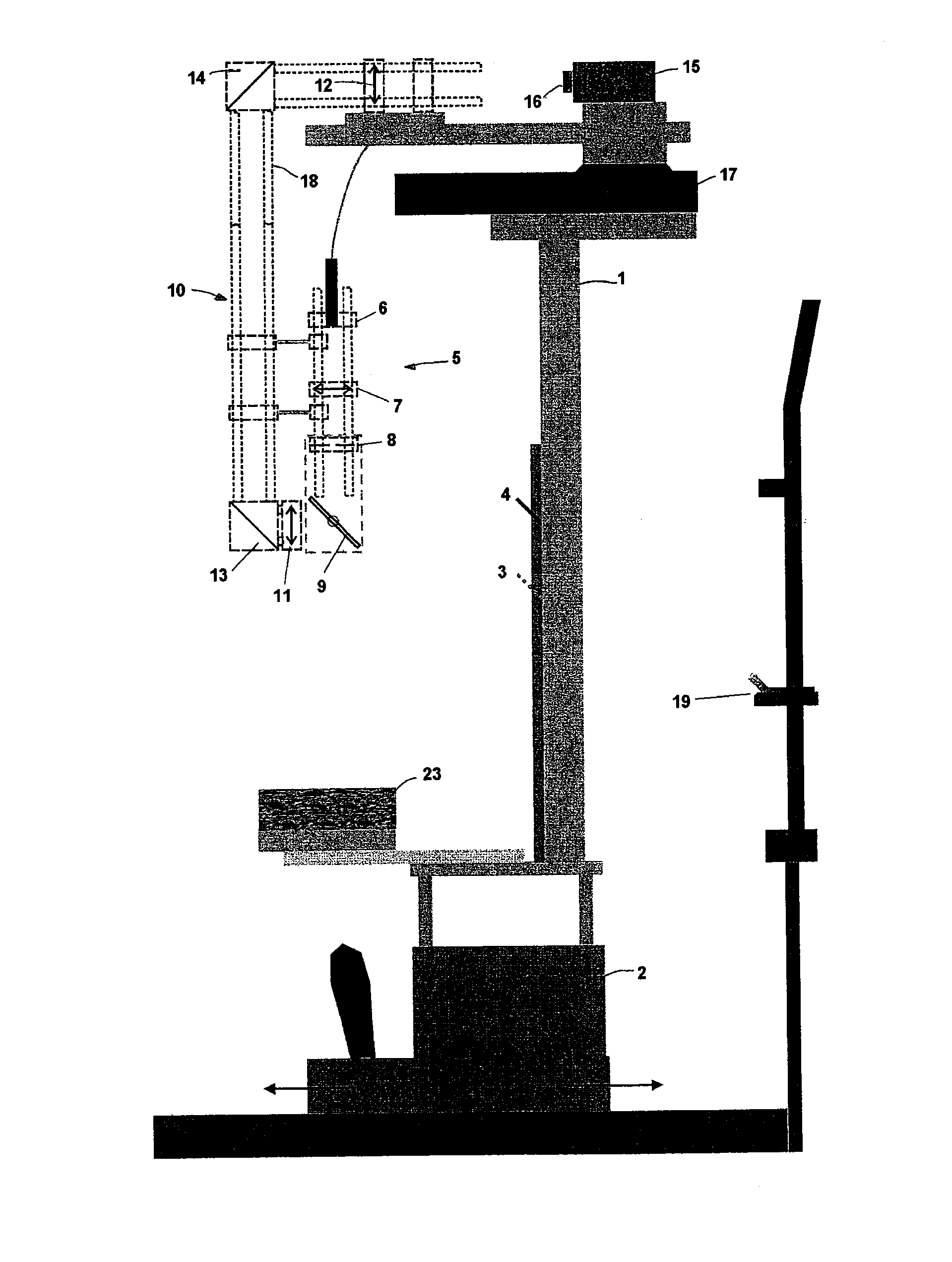
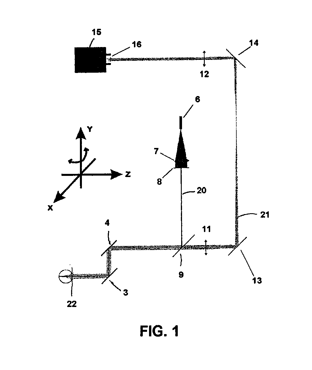
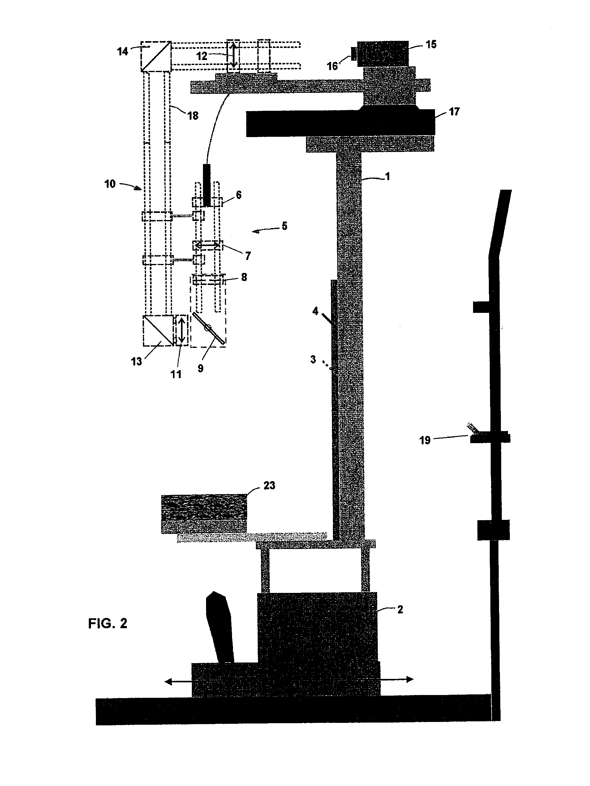
[0035]FIG. 1 shows schematically the optical components that constitute the instrument of the invention, and FIGS. 2 and 3 show the instrument of the invention with all of its components mounted.

[0036]As can be seen in said figures, the instrument comprises a frame 1 mounted on an ophthalmologic table 2, which can be oriented in three perpendicular directions X, Y, Z. Directions X, Z are on the same plane and direction Y is perpendicular to the plane of directions X, Z (see the axes system depicted in FIG. 2).The instrument has a support surface 19 for the head of the subject on whose eyes the measurements are going to be taken. Located in front of the head of the subject and united to frame 1 there is a hot mirror 3 and a long mirror 4.

[0037]The instrument also comprises an illumination sub-assembly 5 consisting of a fibre optic head 6; a lens 7 (L1), a diaphragm 8 (D), a beam splitter 9 (BS), and a measurement sub-assembly 10 with two lens 11 (L2) and 12 (L3), two mirrors 13 (M1) ...


PUM


Abstract

An instrument measuring optical properties of an eye in an entire field of vision, including refraction and aberrations, including: a frame mounted on an ophthalmologic table that can be oriented in three perpendicular directions X, Y, Z; a support surface for a head of the subject; a hot mirror; a long mirror; an illumination sub-assembly including a fiber optic head; a lens; a diaphragm; a beam splitter; and a measurement sub-assembly with two lens and two mirrors; a camera including a matrix of micro-lenses on the inlet of camera, the camera being placed on the focal plane of the micro-lenses; the frame including a motor, a shaft of which rotates in the Y direction, to which an arm is attached that can rotate on the shaft; components of the illumination sub-assembly, components of a measurement sub-assembly, and the camera with the matrix of micro-lenses being mounted on the arm.

Description

FIELD OF THE INVENTION[0001]The present invention refers to an instrument for measuring optical properties, refraction and aberrations of the eye in the entire field of vision, especially for application for prescriptions of new systems of correction, such as eye glasses or contact lenses, that can control myopia in children and adolescents.BACKGROUND OF THE INVENTION[0002]Nowadays, the interest in the quality of the peripheral vision of the human eye (that is, what occurs outside the central zone where details are seen clearly) is greater than ever. This interest began in the 70's with the suggestion that peripheral vision could be an important factor that influences the progression of myopia (see, for example, the publication of F. Rempt, J. Hoogerheide, and W. P. H. Hoogenboom, “Peripheral Retinoscopy and Skiagram”, Ophthalmologica 162, 1-10 (1971), or the publication of J. Hoogerheide, F. Rempt, and W. P. H. Hoogenboom, “Acquired Myopia in Young Pilots”, Ophthalmologica 163, 209...

Claims


Application Information

Patent Timeline
Patent Type & Authority Patents(United States)
IPC IPC(8): A61B3/10A61B3/14A61B3/103A61B3/00
CPCA61B3/103A61B3/1015A61B3/0008A61B3/0083
Inventor JAEKEN, BARTARTAL SORIANO, PABLO
Owner UNIVERSITY OF MURCIA
Why Eureka
Try Eureka