Printer

a printing machine and paper plate technology, applied in printing, typewriters, other printing apparatuses, etc., can solve the problems of increasing feeding resistance, feeding obstruction, and inadequate favorable peeling, so as to achieve the most favorable and effective peeling, the effect of reducing the loose sta

Active Publication Date: 2015-10-27
BROTHER KOGYO KK
View PDF23 Cites 0 Cited by
  • Summary
  • Abstract
  • Description
  • Claims
  • Application Information

AI Technical Summary

Benefits of technology

[0008]It is therefore an object of the present disclosure to provide a printer capable of effectively peeling the print-receiving layer and the adhesive layer without causing an increase in feeding resistance or feeding obstruction.
[0011]As previously described, in the present disclosure, the feeding path of the print-receiving tape comprising the print-receiving layer, the adhesive layer, and the separation material layer is looped back downward by the separation plate, thereby peeling the print-receiving layer and the adhesive layer from the separation material layer (utilizing the fact that the firm print-receiving layer cannot follow the looped back path). At that time, when the print-receiving tape is stretched so that the actual feeding path of the print-receiving tape is linear from the sandwiching position by the platen roller and the printing head to the support position by the separation plate, the peeling can be most favorably and effectively performed. Conversely, in a case where the print-receiving tape is loose from the sandwiching position to the support position unlike the above, the possibility exists that the peeling will not be adequately favorable.
[0012]Hence, according to the present disclosure, the first rib member is provided above the section between the sandwiching position by the platen roller and the printing head and the support position by the separation plate, and this first rib member contacts the print-receiving tape fed through the section from above. With this arrangement, it is possible to lower occurring of a loose state such as described above. As a result, peeling can be performed favorably and effectively.
[0013]At this time, the first rib member and not a flat member, for example, is established, thereby making it possible to reduce the contact surface area when the print-receiving tape is contacted from above. As a result, it is possible to lower the occurrence of feeding obstruction and increases in feeding resistance.

Problems solved by technology

Nevertheless, according to the prior art, when the feeding path of the print-receiving tape is made substantially linear as previously described, the pressing roller contacts the print-receiving tape from above, possibly causing the feeding resistance to increase and feeding obstruction to occur due to such contact.
Conversely, in a case where the print-receiving tape is loose from the sandwiching position to the support position unlike the above, the possibility exists that the peeling will not be adequately favorable.

Method used


Image

  • Printer
  • Printer
  • Printer

Examples


Embodiment Construction

[0063]The following describes one embodiment of the present disclosure with reference to accompanying drawings. First, embodiment 1 of the present disclosure will be described with reference to FIGS. 1-33.

General Outer Appearance Configuration

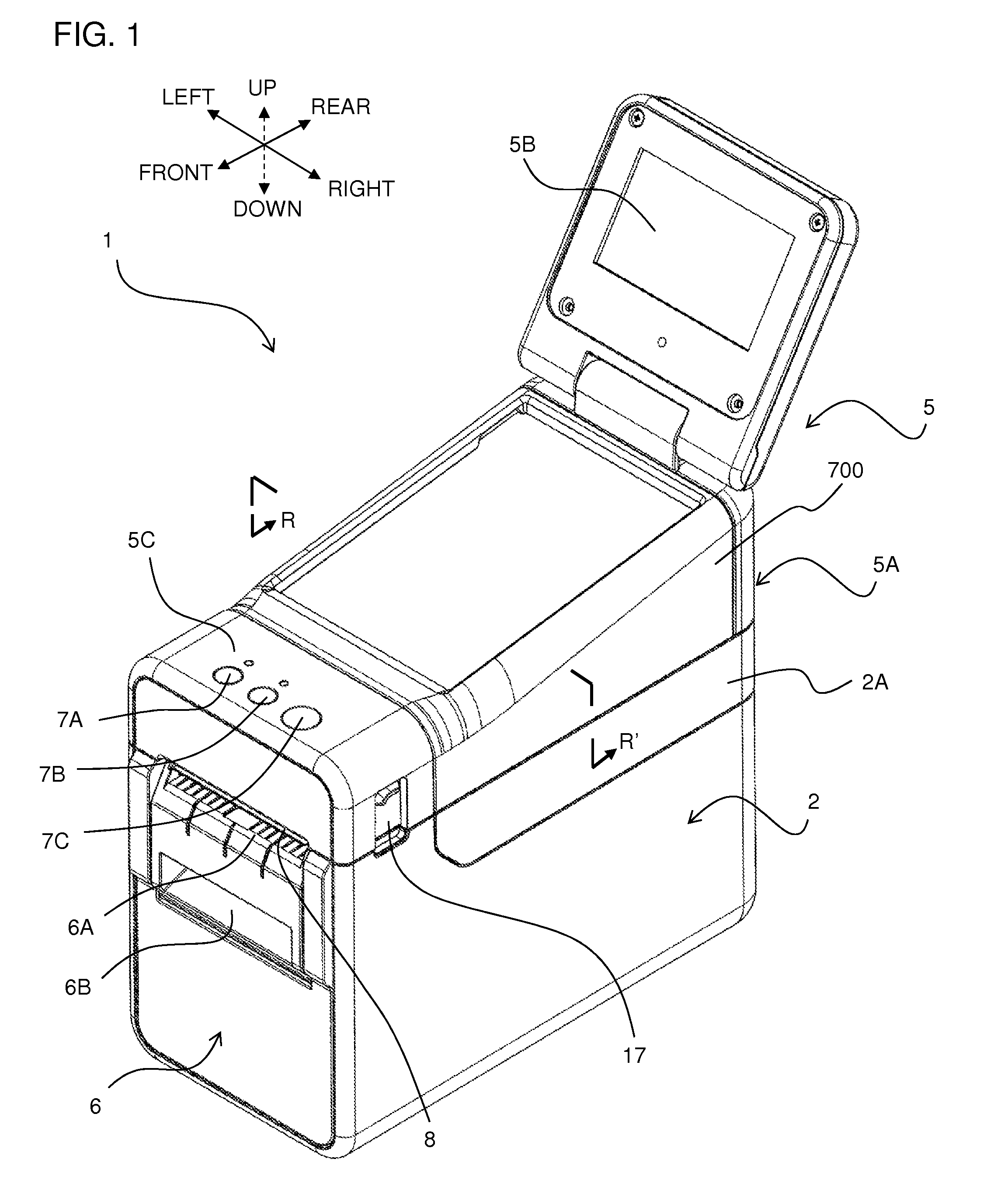
[0064]First, the general outer appearance configuration of a label producing apparatus 1 (printer) of this embodiment will be described using FIG. 1. Note that the front-rear direction, left-right direction, and up-down direction in the descriptions below refer to the directions of the arrows suitably shown in each figure, such as FIG. 1.

[0065]In FIG. 1, the label producing apparatus 1 comprises a housing 2 comprising a front panel 6, and an upper cover unit 5. The housing 2 and the upper cover unit 5 are made of resin, for example. The upper cover unit 5 comprises a touch panel part 5A, a substantially rectangular-shaped liquid crystal panel part 5B, and an operation button part 5C.

[0066]The upper cover unit 5 is pivotably connected to the hou...


PUM


Abstract

This disclosure discloses a printer comprises a roll storage part, a platen roller, a printing head, a separation plate, a first discharging exit, a pinch roller, a second discharging exit, and a first rib member. The platen roller contacts and feeds a print-receiving tape. The printing head is provided above the platen roller. The separation plate is provided on the other side than the platen roller and loops back a separation material layer toward a downward side and peel the print-receiving layer and the adhesive layer from the separation material layer. The first rib member is provided to a first section of a feeding path of the print-receiving tape and contacts the print-receiving tape from above, the first section being between a sandwiching position by the platen roller and the printing head and a support position of an end part of the separation plate.

Description

CROSS-REFERENCE TO RELATED APPLICATION[0001]The present application claims priority from Japanese Patent Application No. 2012-260878, which was filed on Nov. 29, 2012, and Japanese Patent Application No. 2013-109439, which was filed on May 24, 2013, the disclosures of which are incorporated herein by reference in its entirety.BACKGROUND[0002]1. Field[0003]The present disclosure relates to a printer that performs printing on a print-receiving tape.[0004]2. Description of the Related Art[0005]There are known printers (label printers) configured to form desired print on a print-receiving tape (strip-shaped mount) comprising a print-receiving layer (label), adhesive layer, and a separation material layer. According to this printer, the feeding path of the print-receiving tape after print formation loops back downward, thereby peeling the print-receiving layer and the adhesive layer from the separation material layer, utilizing the fact that the firm print-receiving layer cannot follow t...

Claims


Application Information

Patent Timeline
Patent Type & Authority Patents(United States)
IPC IPC(8): B41J29/02B41J15/04B41J3/407B41J29/13
CPCB41J15/042B41J3/4075B41J29/02B41J29/13
Inventor JO, HIDENORISEO, KEIJIUCHINO, KUMIKOHOKAZONO, TAKAMINENAGASHIMA, YUKIOHNISHI, HIROKI
Owner BROTHER KOGYO KK
Why Eureka
Try Eureka