Method for cleaning vacuum apparatus, device for controlling vacuum apparatus, and computer-readable storage medium storing control program

a technology for vacuum apparatus and cleaning method, which is applied in the direction of program control, chemistry apparatus and processes, instruments, etc., can solve the problems of preventing the appropriate cleaning, difficult to correctly evaluate the cleanliness of the vacuum apparatus, and difficult to clean the proportions, so as to achieve dramatic improvement of product yield and the effect of high vacuum apparatus cleanliness

Inactive Publication Date: 2008-06-26
TOKYO ELECTRON LTD
View PDF6 Cites 12 Cited by
  • Summary
  • Abstract
  • Description
  • Claims
  • Application Information

AI Technical Summary

Benefits of technology

[0015]A purge gas at a predetermined pressure or more is thus rapidly flowed into the vacuum apparatus. The rapid purge gas generates a shock wave in the vacuum apparatus. The shock wave provides physical oscillations. The oscillations may effectively peel off the deposits attached to the interior of the vacuum apparatus and the movable parts disposed therein.
[0038]Thus, according to an aspect of the present invention, the deposits attached to the vacuum apparatus and the movable parts disposed therein may be effectively removed.

Problems solved by technology

Unfortunately, JP 2003-168679 discloses that the cleaning-gas lines have a complicated configuration in which the lines direct the gas nozzles toward respective movable parts in the interior of the vacuum apparatus.
Those portions are hard to clean.
It may thus be hard to correctly evaluate the cleanliness of the vacuum apparatus, preventing the appropriate cleaning.

Method used


Image

  • Method for cleaning vacuum apparatus, device for controlling vacuum apparatus, and computer-readable storage medium storing control program
  • Method for cleaning vacuum apparatus, device for controlling vacuum apparatus, and computer-readable storage medium storing control program
  • Method for cleaning vacuum apparatus, device for controlling vacuum apparatus, and computer-readable storage medium storing control program

Examples


first embodiment

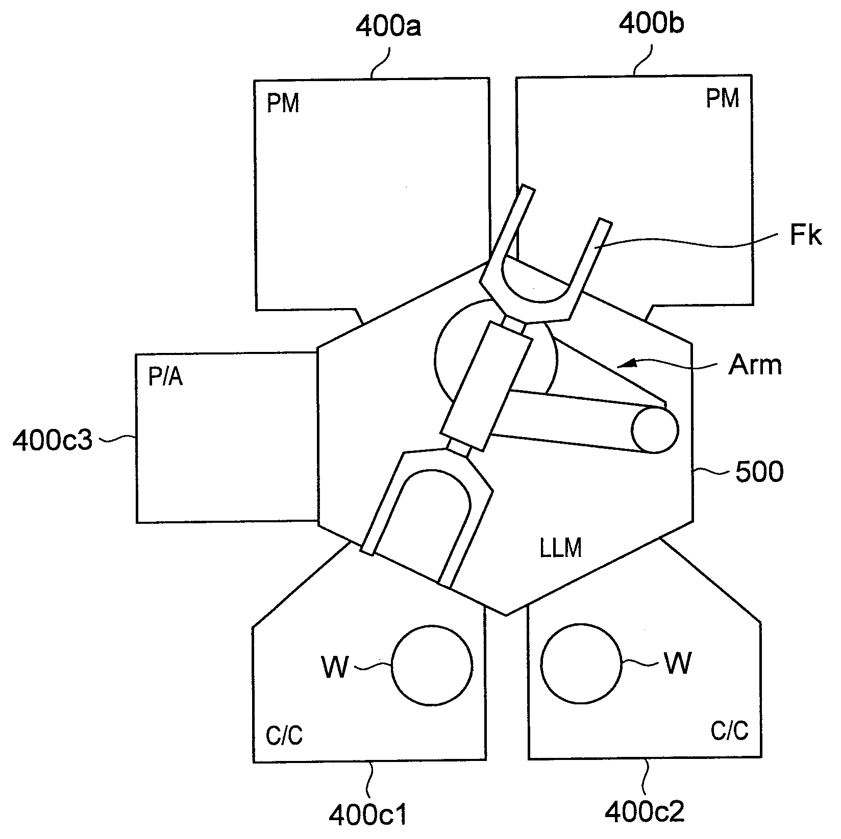
[0052]With reference to FIG. 1, a substrate processing system according to a first embodiment of the present invention will be generally described. Note that this embodiment describes a method for cleaning deposits attached to the interior of the vacuum chamber and the movable parts disposed therein, the deposits being formed during etching of the silicon wafer (hereinafter, referred to as the wafer W) using the substrate processing system.

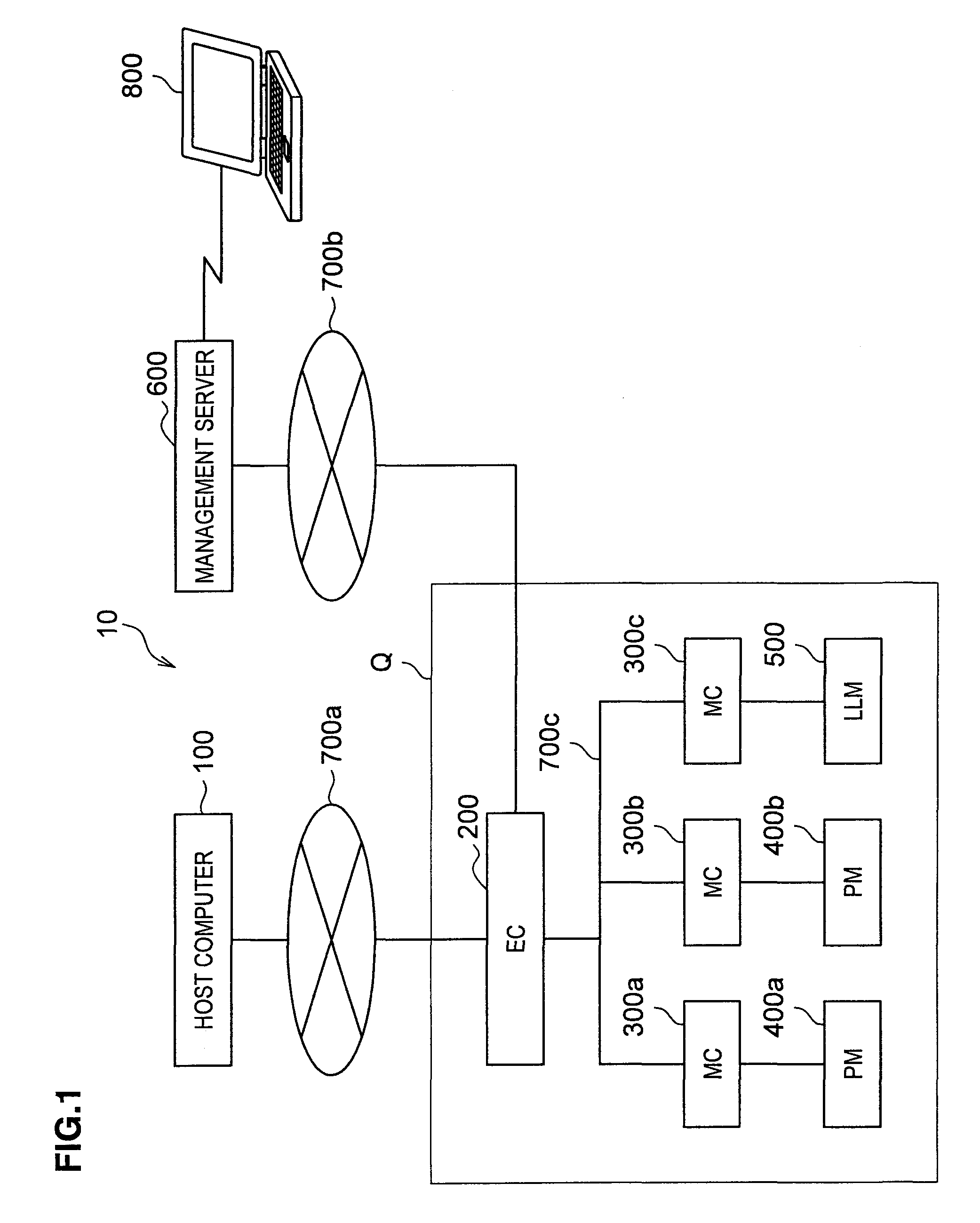
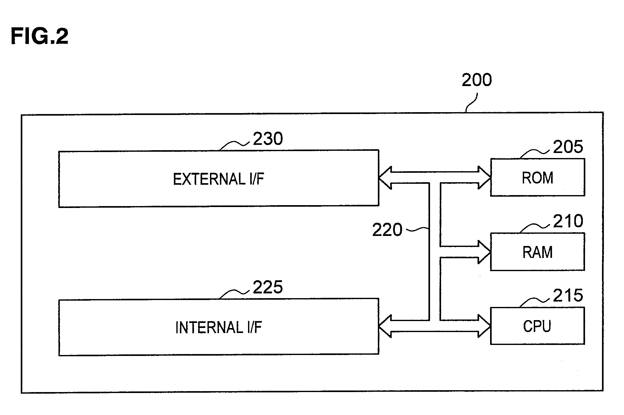
[0053](Substrate processing system) A substrate processing system 10 includes a host computer 100, an equipment controller (hereinafter called the “EC”) 200, three machine controllers (hereinafter called the “MCs”) 300a to 300c, two process modules (hereinafter called the “PMs”) 400a and 400b, one load lock module (hereinafter called the “LLM”) 500, and a management server 600.

[0054]The host computer 100 and the EC 200 are connected by a client local area network (LAN) 700a, and the EC 200 and the management server 600 are connected in a client LA...

second embodiment

[0105]The cleaning method according to a second embodiment of the present invention will be described. The second embodiment differs from the first embodiment in that the particle monitor Mr is used to detect the number of particles, and when the detected number is less than a predetermined threshold, the cleaning is ended. In the first embodiment, the cleaning is ended according to the specification in the recipe. Focusing on the difference between the two embodiments, the cleaning method according to this embodiment will be described below with reference to FIG. 11.

[0106]In the second embodiment, step 615 in FIG. 6 calls the auto-setup process in FIG. 11. After step 1100, at steps 805 and 810, the cleaning execution unit 275 loads the dummy wafers and performs the NPPC as in the first embodiment. Control then passes to step 1105, where a not-shown timer is set to “0.” Then at step 815, the movable parts are repeatedly moved. Then at step 820, the NPPC is performed again.

[0107]Cont...

third embodiment

[0114]A cleaning method according to a third embodiment of the present invention will be described below. The third embodiment differs from the second embodiment in that the particle monitor Mr is used to detect the number of particles, and when the detected number is less than a predetermined threshold, the cleaning is ended, and then each movable part is moved separately, thereby identifying the particle source. In the second embodiment, the particle source is not identified. Focusing on the difference between the two embodiments, the cleaning method according to this embodiment will be described below with reference to FIG. 12.

[0115]In the third embodiment, step 615 in FIG. 6 calls the auto-setup process in FIG. 12. The cleaning execution unit 275 performs, as in the second embodiment, steps 1200, 805, 810, and 1105. The execution unit 275 then repeats steps 815, 820, 1110, and 1115, thereby continuing the cleaning process until the number of particles is less than a threshold or...


PUM


Abstract

A vacuum apparatus such as PM 400 or LMM 500 includes: a chamber to transfer or process a wafer; a plurality of movable parts in the chamber; a high-voltage power supply 485 to introduce a high voltage HV to the chamber; a gas supply unit 445 to supply a gas to the chamber; and an exhaust mechanism 490 to exhaust a purge gas in the chamber. The vacuum apparatus is cleaned by supplying the purge gas from the gas supply unit 445 and exhausting the purge gas in the chamber via the exhaust mechanism 490, repeating a motion of each movable part, and controlling the purge-gas pressure to be equal to or more than a predetermined pressure before and / or during and / or after the repeated motions of each movable part, and / or allowing the power supply 485 to intermittently output the HV before and / or after the motions of each movable part.

Description

CROSS-REFERENCE TO RELATED APPLICATIONS[0001]The present invention contains subject matter related to Japanese Patent Application No. 2006-346241, filed on Dec. 22, 2006 and Provisional Application No. 60 / 896, 358, filed on Mar. 22, 2007, the entire contents of which being incorporated herein by reference.BACKGROUND OF THE INVENTION[0002]1. Field of the Invention[0003]The present invention relates to a method for cleaning a vacuum apparatus, a control device for controlling the cleaning of the vacuum apparatus, and a computer-readable storage medium storing the control program. More particularly, the present invention relates to a method for cleaning a vacuum apparatus and a movable part disposed therein.[0004]2. Description of the Related Art[0005]Vacuum apparatuses allow process gases to be used therein to perform desired processes on target objects. During the processes, reaction products from the process gases are attached to the inside of vacuum chambers and are gradually depos...

Claims


Application Information

Patent Timeline
Patent Type & Authority Applications(United States)
IPC IPC(8): G06F9/00B08B5/00
CPCH01L21/02041
Inventor NAKAMURA, HIROSHI
Owner TOKYO ELECTRON LTD
Why Eureka
Try Eureka