Apparatus for removing cover of golf ball from core

a golf ball and core technology, applied in the field of golf ball cover peeling machine, can solve the problems of shortened flight distance, damage to the cover surface, wear of the dimples, etc., and achieve the effect of reducing the thickness of the cover and facilitating heating

Inactive Publication Date: 2007-04-17
DUNLOP SPORTS CO LTD
View PDF9 Cites 13 Cited by
  • Summary
  • Abstract
  • Description
  • Claims
  • Application Information

AI Technical Summary

Benefits of technology

[0013]In the cover peeling machine, the tip of the tapered roll has a small diameter. Therefore, in the case in which the golf ball is mounted close to the tip, a distance between the lower end of the ball and the nip of the roll is reduced. Accordingly, if a projection (clip portion) is previously formed on the cover, the roll can easily bite the clip portion. As a result, the cover is reliably entangled and is peeled from the core through the rotation of the roll. Moreover, the rear end of the roll has a large diameter and the rotary shaft of the roll can also have a large diameter. Therefore, it is also possible to support and rotate the roll like a cantilever. Furthermore, when the clip portion is once bitten into the nip, the cover is pulled obliquely downward. Consequently, the ball is moved toward the large diameter side over the roll. Thus, the cover can be peeled efficiently.
[0034]By the removing apparatus, the cover can be removed from the core efficiently without a manual operation.

Problems solved by technology

If the golf ball is used repetitively, the surface of the cover is damaged and dimples are also worn.
As a result, the appearance is deteriorated and a flight distance is shortened during the lifetime of the ball.
In view of this, most used golf balls are wasted.
In recent years, a large amount of golf balls have been wasted with an increase in production of the golf ball, which has caused problems.
In order to interpose the convex portion by mating the teeth with each other, it is necessary to press the rolls against each other and the teeth of the rolls are damaged easily.
In addition, there is a possibility that the surface of the core might be damaged by the teeth during the removal.
For this reason, when the golf ball is put on the rolls, the convex portion cannot reach a roll nip and the cover cannot be removed in some cases.
However, the roll having a small diameter is fragile so that troubles are practically made in respect of durability.
Furthermore, it is necessary to stably form a convex portion having a uniform dimension in order to reliably bite the convex portion, which cannot be carried out readily.

Method used


Image

  • Apparatus for removing cover of golf ball from core
  • Apparatus for removing cover of golf ball from core
  • Apparatus for removing cover of golf ball from core

Examples


examples

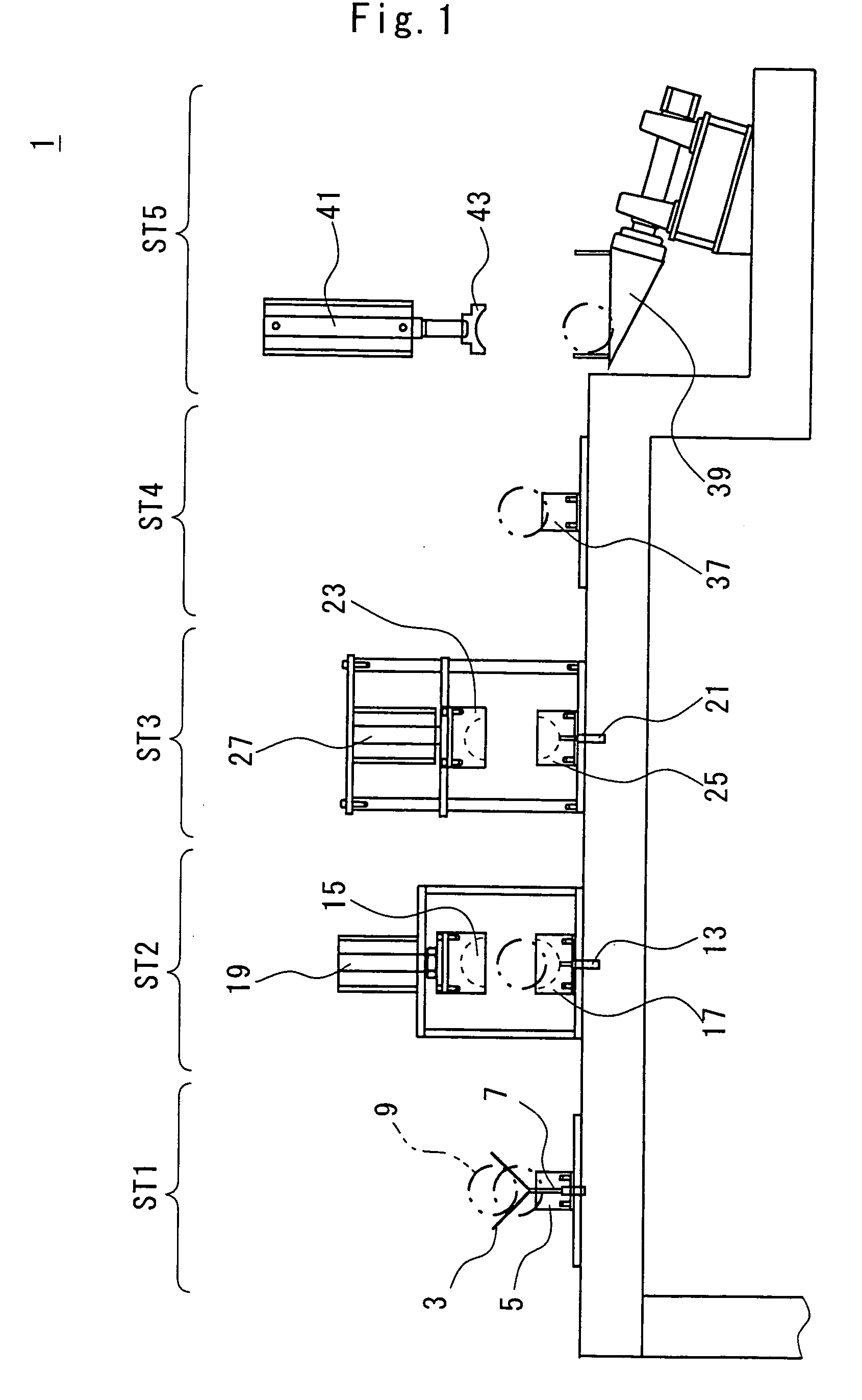
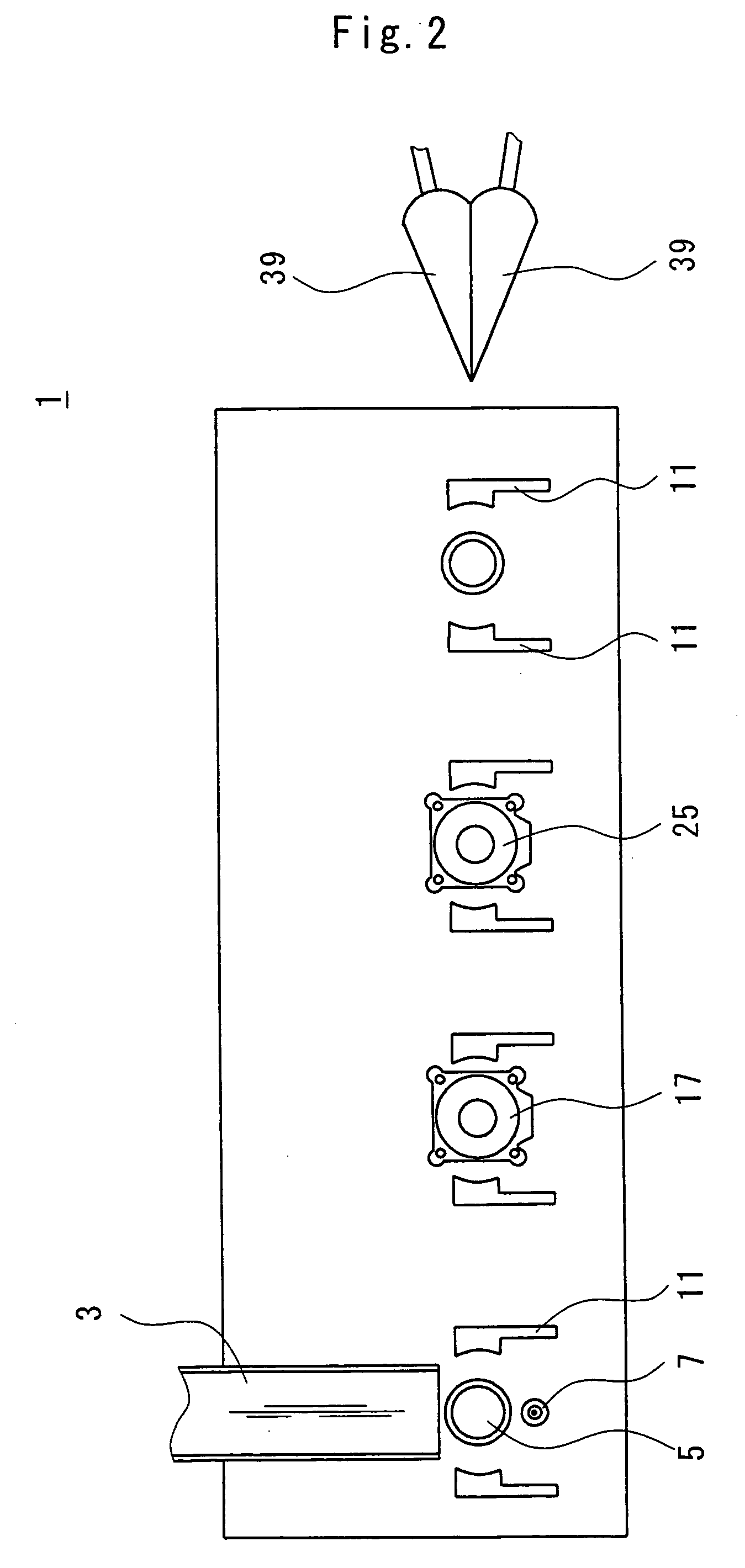
[0074]A two-piece golf ball (having a diameter of 42.7 mm) comprising a core having a diameter of 38.9 mm formed of a solid rubber and a cover having a thickness of 1.9 mm and containing an ionomer resin as a principal component was prepared. The cover was removed from the core by the removing apparatus shown in FIGS. 1 and 2 in the following procedure.

[0075]First of all, a ball delivered from a first station was heated in a second station. A cup having an inside diameter of 43.0 mm and a cavity surface coated with Teflon was used. A heating temperature was set to 140° C. and a time required for heating was set to approximately 20 seconds.

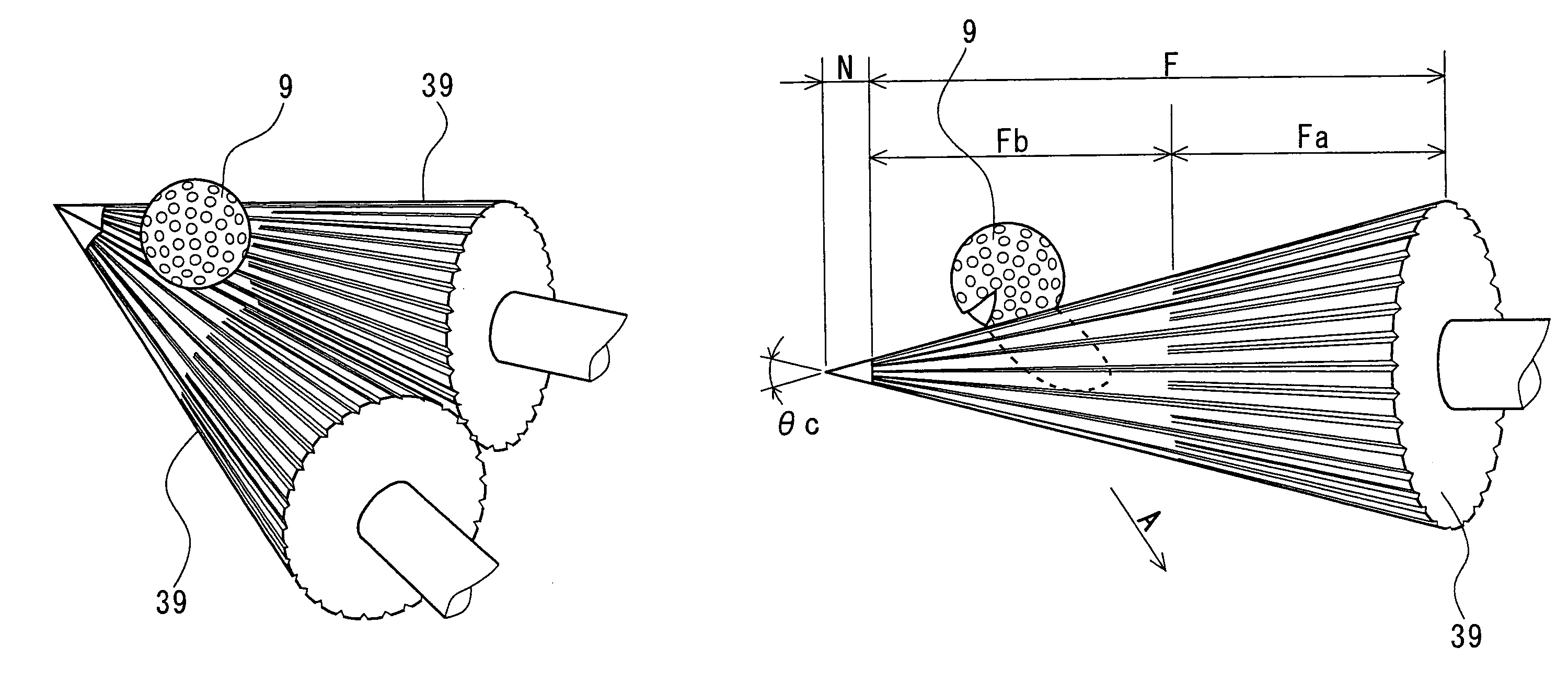
[0076]Next, a clip portion was formed in the second station. A cup having an inside diameter of 39.0 mm and a cavity surface coated with Teflon was used. A temperature of the cup was set to 140° C. and approximately 20 seconds were taken to form the clip portion. The clip portion thus obtained had a thickness Tk of approximately 4 mm and a width W ...


PUM

PropertyMeasurementUnit
vertical anglesaaaaaaaaaa
diametersaaaaaaaaaa
vertical angleaaaaaaaaaa

Abstract

A cover peeling machine includes a pair of rolls. The roll has an almost conical shape. Both of the rolls are rotated in a reverse direction. The direction of the rotation is an inward direction as seen from above. A golf ball is put close to a tip of the roll. In the vicinity of the tip, a distance between a nip of the roll and the golf ball is short. Therefore, a clip portion formed on the golf ball can be easily bitten between the rolls. With the rotation of the roll, a cover is peeled from a core. A groove formed on a surface of the roll can prevent the roll and the cover from slipping. After the removal, the cover and the core are recycled respectively.

Description

[0001]This application is a Divisional of co-pending Application No. 09 / 961,491, filed on Sep. 25, 2001, now U.S. Pat. No. 6,833,098, and for which priority is claimed under 35 U.S.C. § 120; and this application claims priority of Application No. 2000-295493 filed in Japan on Sep. 28, 2000 under 35 U.S.C. § 119; the entire contents of all are hereby incorporated by reference.BACKGROUND OF THE INVENTION[0002]1. Field of the Invention[0003]The present invention relates to a machine for peeling a cover of a golf ball, a method of removing the cover from a core, an apparatus for removing the cover from the core and a method of manufacturing a golf ball formed of a regenerated material.[0004]2. Description of the Related Art[0005]A golf ball is roughly divided into a wound ball and a solid ball. The solid ball comprises a core having a single or more rubber layers and a synthetic resin cover coated over a surface of the core. If the golf ball is used repetitively, the surface of the cove...

Claims


Application Information

Patent Timeline
Patent Type & Authority Patents(United States)
IPC IPC(8): B32B38/10A01B29/04B30B3/04A63B37/00A63B45/00B26F3/02B29B17/02B29C63/00
CPCA63B45/00B26F3/02B29B17/02B29C63/0013A63B37/0003B29B2017/044Y10T156/19B29L2031/7734Y10S156/919Y10S264/911Y10T156/11Y10T156/1153Y10T156/1956B29L2031/54B29L2031/546Y02W30/52Y02W30/62
Inventor WATABE, YASUHIROYAMAKAWA, JUNNISHIKAWA, OSAMUTAKAMI, MASAO
Owner DUNLOP SPORTS CO LTD
Why Eureka
Try Eureka