Firearm trigger assembly

a technology for trigger assemblies and firearms, applied in the field of firearms, can solve the problems of affecting the function affecting the performance of the trigger assembly over time, and affecting the functionality of the trigger assembly,

Active Publication Date: 2015-10-27
KRIEGER JOHN M
View PDF54 Cites 15 Cited by
  • Summary
  • Abstract
  • Description
  • Claims
  • Application Information

AI Technical Summary

Benefits of technology

[0008]The present invention provides embodiments of systems and methods related to firearm trigger assemblies, which overcome one or more of the above mentioned drawbacks. In general, trigger assemblies according to the present invention will assist in preventing the accumulation of dust and other particulates within the assembly, and will assist in providing easy cleaning access in the event that any foreign particulates do interfere with operation.
[0012]An embodiment of a firearm trigger assembly according to the present invention includes three levers, a first lever, a second lever, and a third lever. The first lever extends between a first lever first end and a first lever second end and includes a second-lever engagement means, which may comprise a notch and may be located closer to the first lever first end than to the first lever second end. The first lever is pivotable about a first lever axis and the first lever is biased in a first rotational direction about the first lever axis, which may be located closer to the first lever second end than to the first lever first end. The second lever extends between a second lever first end and a second lever second end and includes a protrusion, such as a wedge, formed thereon. The second lever is pivotable about a second lever axis and the second lever is biased in a second rotational direction about the second lever axis, which is at least substantially parallel with the first lever axis. The third lever extends between a third lever first end and a third lever second end and including a lower rocker surface and an upper pin surface, wherein the third lever is pivotable about a third lever axis, which is at least substantially parallel to the first lever axis. The levers generally cooperate in such a way to maintain a firearm firing pin in a cocked position. The second-lever engagement means rests in contact with the protrusion to prevent rotation of the second lever opposite the second and the third lever is prevented from rotating in a third rotational direction about the third lever axis by the contact of the lower rocker surface with the second lever.

Problems solved by technology

As previously mentioned, two factors can contribute to undesirable inaccuracy and inconsistency in firearm trigger assemblies: friction and foreign particulates.
Repeated firing actions begin to wear down both the sear pin and the portion of the firing pin, thereby altering the performance of the trigger assembly over time.
However, it has been discovered that, contrary to the conventional wisdom that shielding moving parts from dust should improve functionality, the housing, or closed design, actually impedes functionality over time by allowing foreign particulates to accumulate therein.
Unfortunately, such disassembly creates the risk that the small springs, screws and ball bearings will be lost or damaged.
Additionally, foreign particulates may extend what would otherwise be considered a normal lock time.

Method used


Image

  • Firearm trigger assembly
  • Firearm trigger assembly
  • Firearm trigger assembly

Examples


Embodiment Construction

[0026]Although the disclosure hereof is detailed and exact to enable those skilled in the art to practice the invention, the physical embodiments herein disclosed merely exemplify the invention which may be embodied in other specific structures. While the preferred embodiment has been described, the details may be changed without departing from the invention, which is defined by the claims.

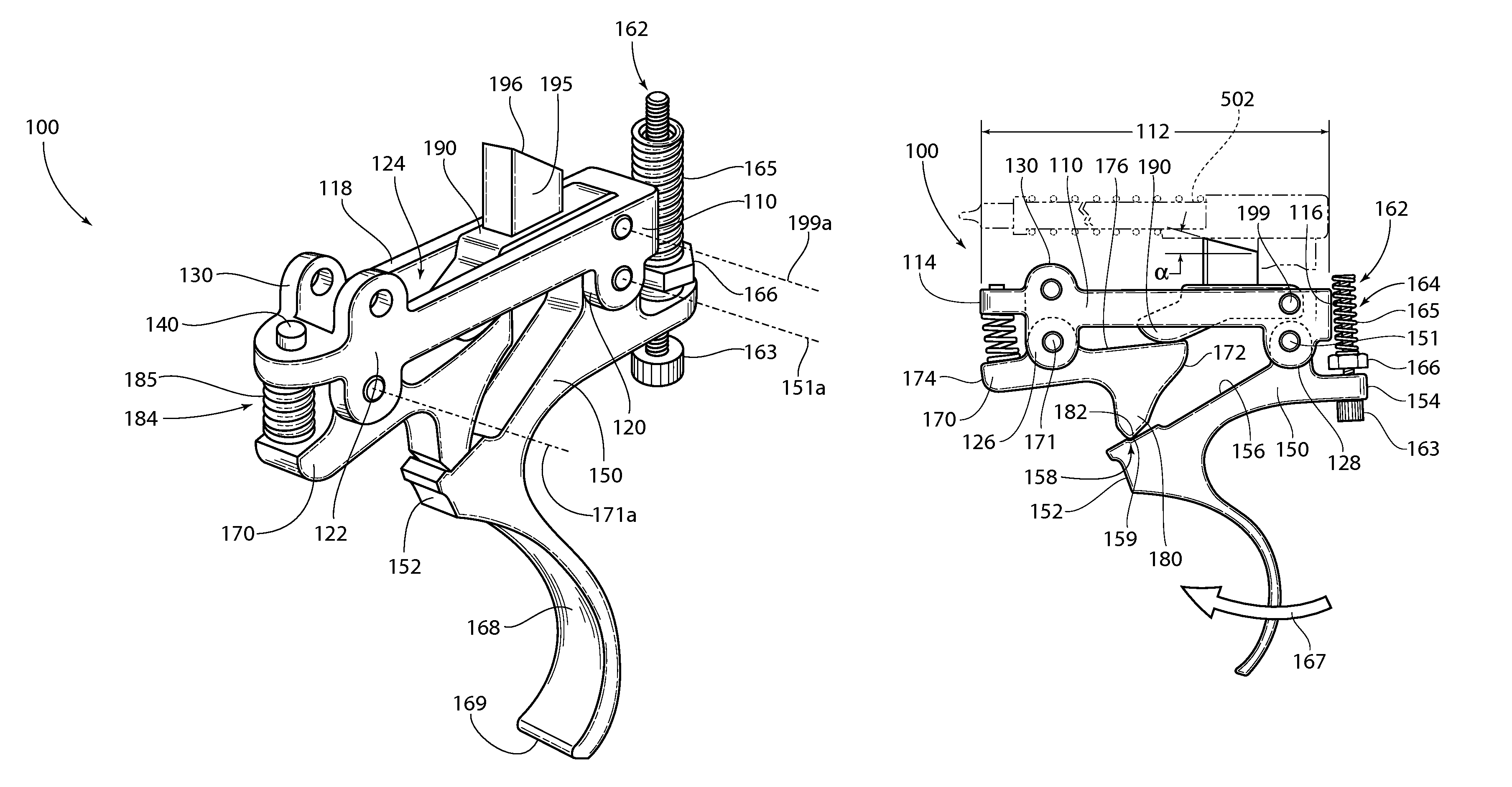
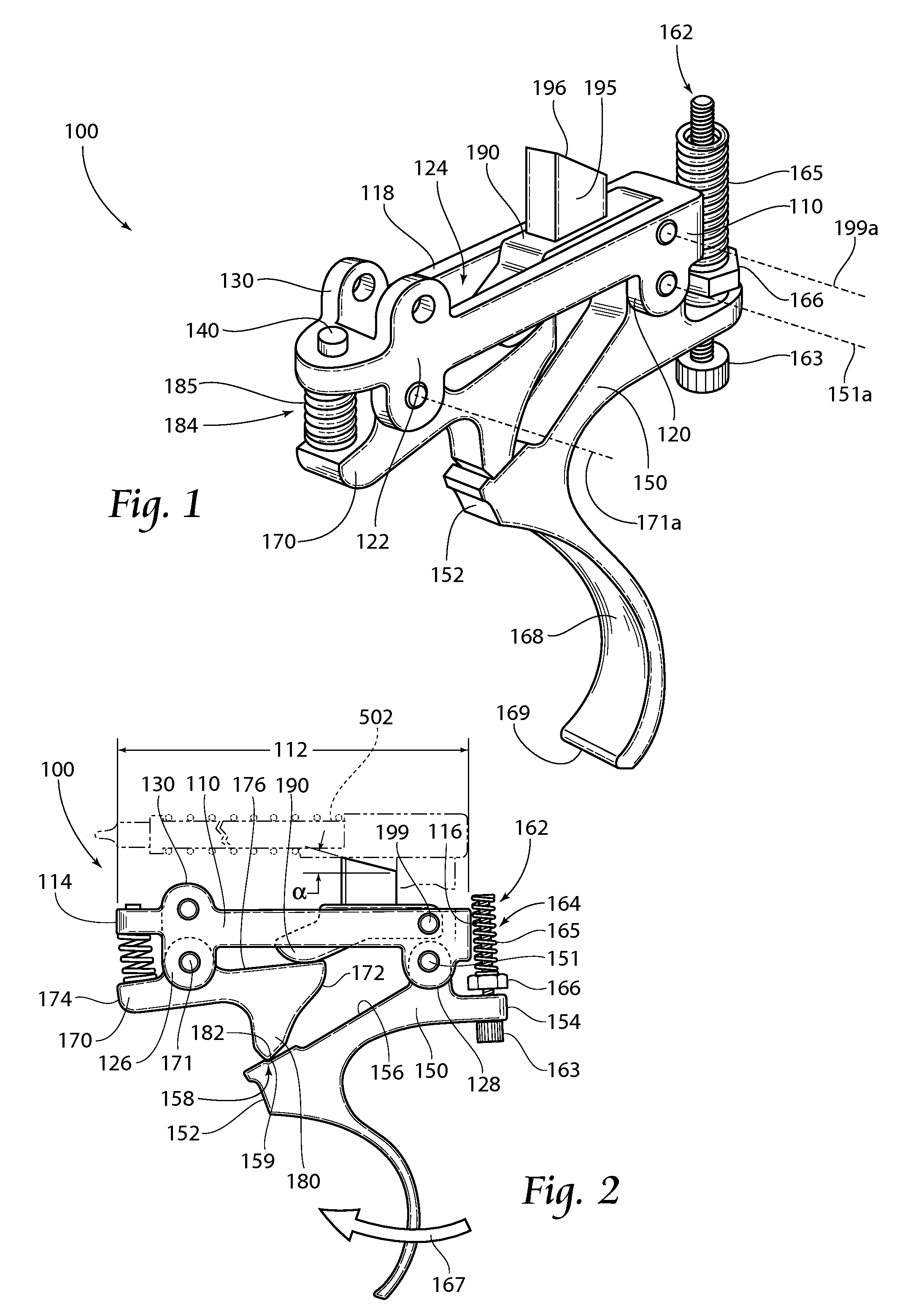
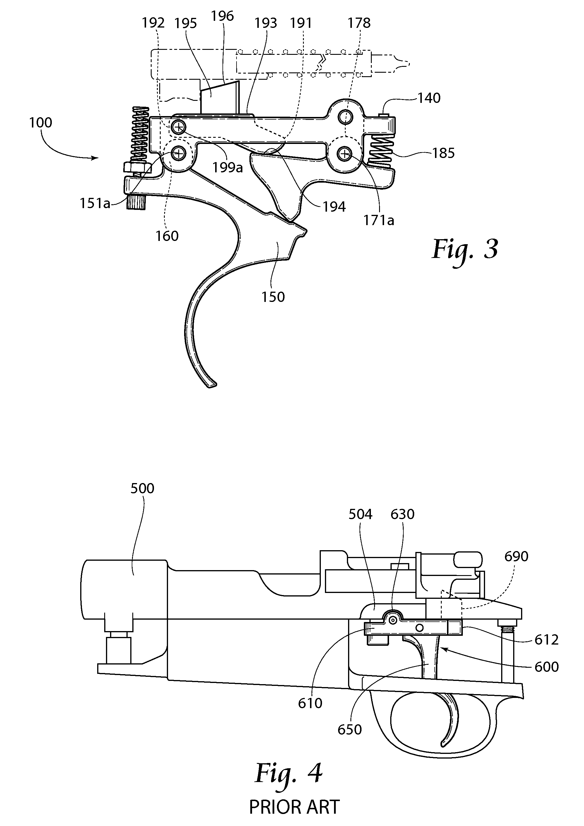
[0027]Turning now to the figures, FIGS. 1-3 depict a first embodiment 100 of a trigger assembly according to the present invention. The trigger assembly 100 generally includes a support bracket 110, a trigger lever 150, a transfer lever 170, and a sear lever 190. The support bracket 110 extends longitudinally throughout a bracket length 112 from a first bracket end 114 to a second bracket end 116. The support bracket 110 has a top side 118 and a bottom side 120 coupled together by lateral sides 122, which extend between the first bracket end 114 and the second bracket end 116. Formed along at leas...


PUM

PropertyMeasurementUnit
angleaaaaaaaaaa
angleaaaaaaaaaa
angleaaaaaaaaaa

Abstract

Provided are systems and methods related to firearm trigger assemblies. An open design trigger assembly is provided to allow easier access to the trigger action. The trigger assembly is preferably an override trigger assembly, which may include adjustable trigger travel limiter and trigger bias force. Methods according to the present invention include a first step of removing either a direct-pull or a closed design trigger assembly from a firearm and replacing such removed assembly with an open design override trigger assembly.

Description

RELATED APPLICATIONS[0001]This application claims the benefit of U.S. Provisional Patent Application Ser. No. 61 / 395,358, filed 12 May 2010.BACKGROUND OF THE INVENTION[0002]The present invention relates generally to firearms, but more particularly to systems and methods regarding firearm trigger assemblies.[0003]Generally, consistency and accuracy are understandably important in the art of firearms, especially in the field of competitive marksmanship. Regarding firearm trigger assemblies, inconsistency and inaccuracy may be attributed to at least two factors: friction and foreign particulates.[0004]In the art of firearms, trigger assemblies may generally be coarsely divided into two types: direct-pull and override. Each trigger assembly type includes a sear pin which is adapted to abut a firing pin in the associated firearm. However, the two types of trigger assemblies differ in the way that the sear pin maintains the firing pin in a retracted, pre-firing state. A direct-pull trigge...

Claims


Application Information

Patent Timeline
Patent Type & Authority Patents(United States)
IPC IPC(8): F41A19/10F41A19/16
CPCF41A19/10F41A19/16Y10T29/49826
Inventor KRIEGER, JOHN M.
Owner KRIEGER JOHN M
Why Eureka
Try Eureka