Eureka AIR delivers breakthrough ideas for toughest innovation challenges, trusted by R&D personnel around the world.

Inductive position sensor

Active Publication Date: 2015-10-27
NASA
View PDF4 Cites 2 Cited by
  • Summary
  • Abstract
  • Description
  • Claims
  • Application Information

AI Technical Summary

Benefits of technology

The present invention is about a device that uses three inductors to measure position. These inductors have separate cores and are placed in a common medium, like air. The inductors are immersed in a common medium, and they are designed to move relative to each other while keeping their cores parallel. The device measures the phase of an oscillating current, and the phase of the voltage induced in the third inductor. The device has fixed capacitance between the inductors. The technical effect of this device is a more accurate and precise way to measure position in a simple and effective way.

Problems solved by technology

While each type of position sensor has its advantages, each also presents disadvantages for some applications.
For example, the size of capacitors can make their use impractical when the position sensor must be small in size.
The complexity and / or cost of laser-based sensors and eddy-current-based sensors can negate their advantages in a number of applications.

Method used


Image

  • Inductive position sensor
  • Inductive position sensor
  • Inductive position sensor

Examples


Embodiment Construction

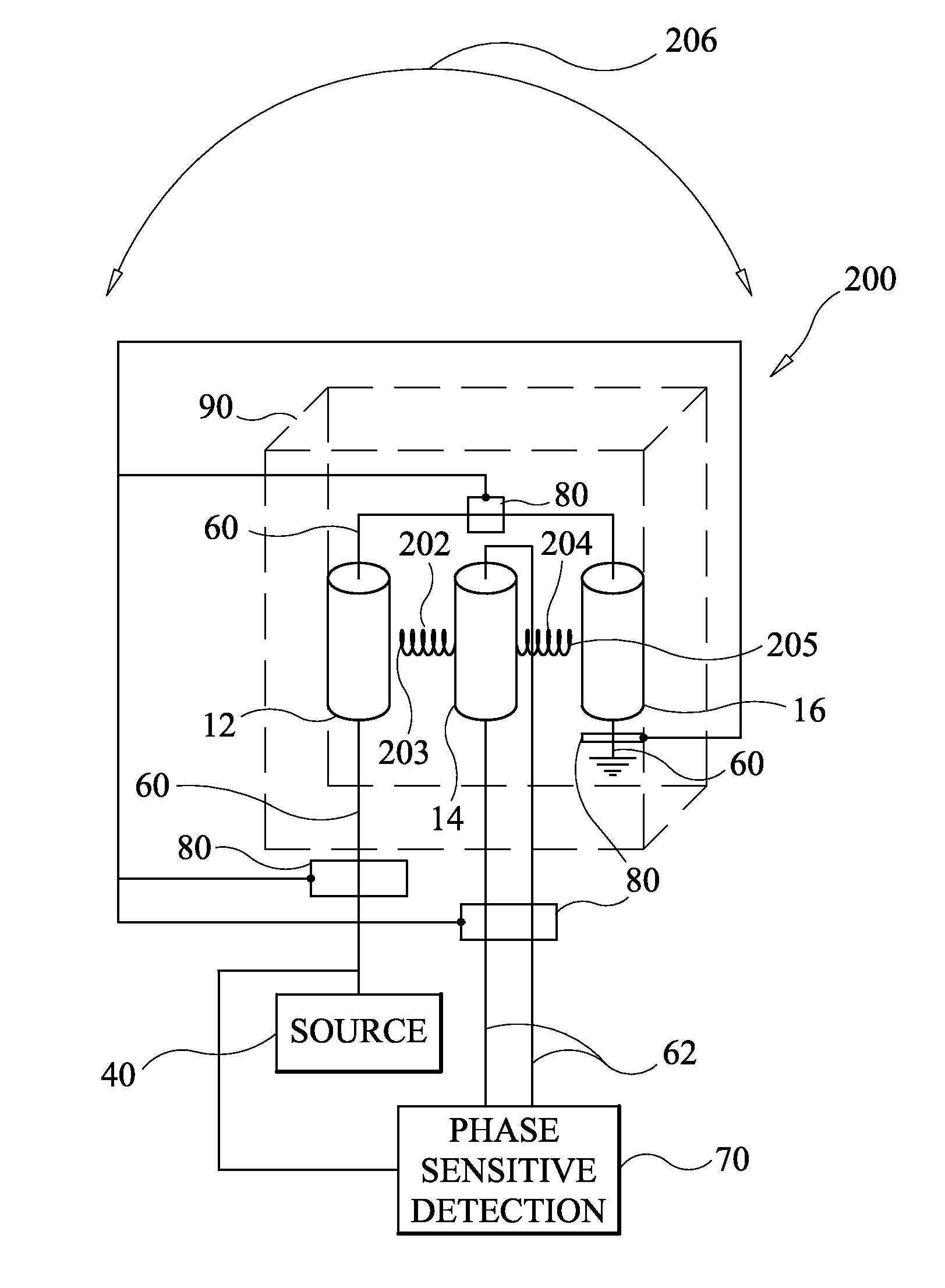
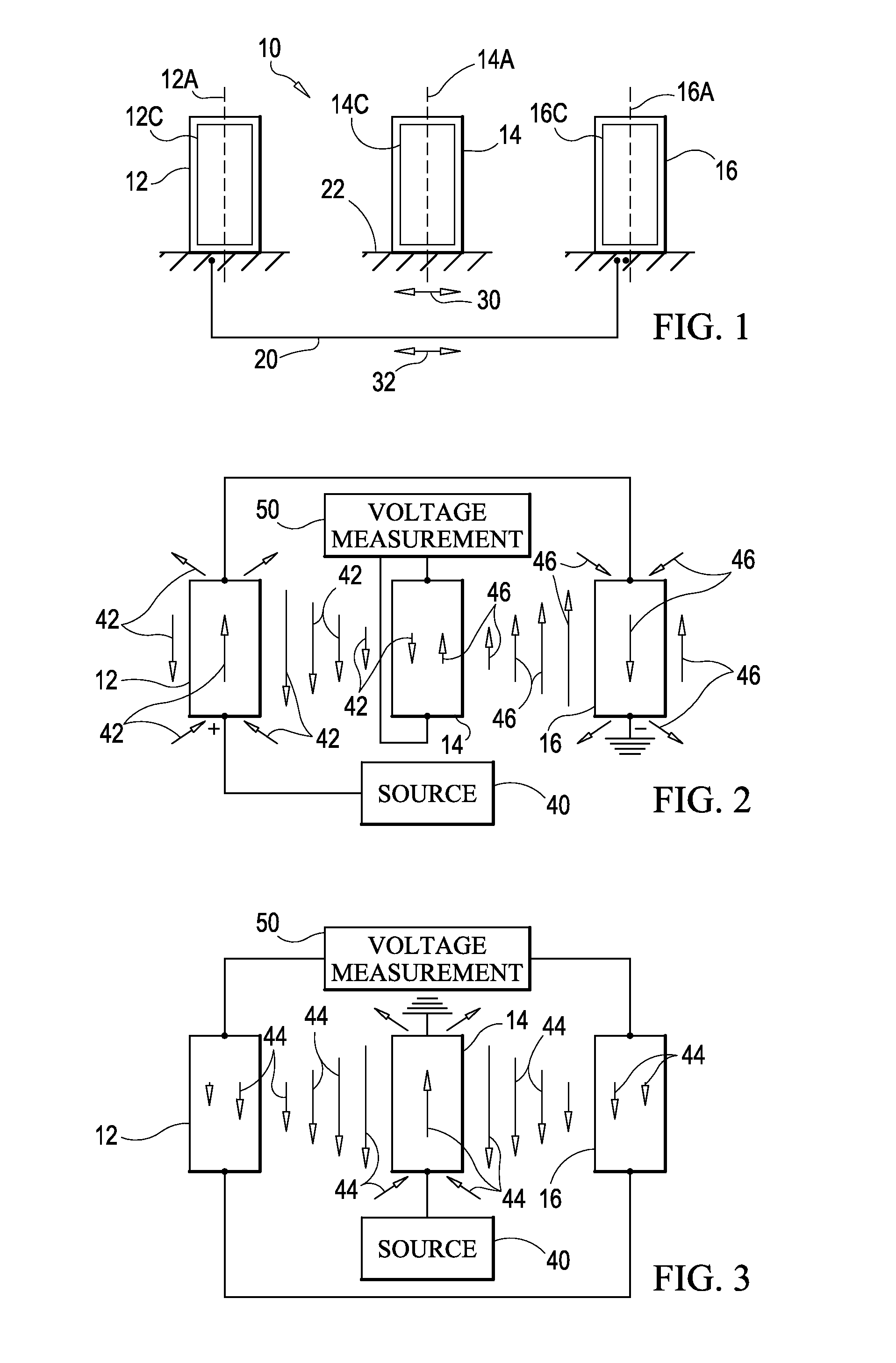
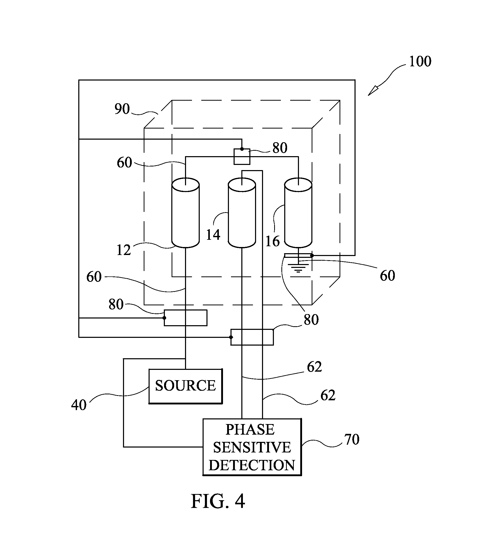
[0015]Referring now to the drawings and more particularly to FIG. 1, an inductive position sensor in accordance with an embodiment of the present invention is shown and is referenced generally by numeral 10. For clarity of illustration, only the mechanical aspects of three inductors used in inductive position sensor 10 are illustrated in FIG. 1. The electrical and other construction aspects in various embodiments of inductive position sensor 10 will be presented later herein.

[0016]Inductive position sensor 10 uses spaced-apart and adjacent inductors 12, 14, and 16. For purposes of the present invention, each of inductors 12, 14, and 16 is an independent inductor structure defined by a coil of wire (not shown) wrapped about its own separate and mechanically independent ferromagnetic core 12C, 14C, and 16C, respectively, in accordance with constructions well known and understood in the art. That is, each of magnetic cores 12C, 14C, and 16C is an individual magnetic structure. The indu...


PUM


Abstract

An inductive position sensor uses three parallel inductors, each of which has an axial core that is an independent magnetic structure. A first support couples first and second inductors and separate them by a fixed distance. A second support coupled to a third inductor disposed between the first and second inductors. The first support and second support are configured for relative movement as distance changes from the third inductor to each of the first and second inductors. An oscillating current is supplied to the first and second inductors. A device measures a phase component of a source voltage generating the oscillating current and a phase component of voltage induced in the third inductor when the oscillating current is supplied to the first and second inductors such that the phase component of the voltage induced overlaps the phase component of the source voltage.

Description

CROSS-REFERENCE TO RELATED APPLICATIONS[0001]This application is a continuation-in-part of U.S. application Ser. No. 12 / 961,344, filed Dec. 6, 2010, which claims benefit under 35 U.S.C. §119(e) of U.S. Provisional Application Ser. No. 61 / 267,130, filed on Dec. 7, 2009, the contents of which are incorporated herein by reference.ORIGIN OF INVENTION[0002]The invention described herein was made in the performance of work under a NASA contract and by an employee of the United States Government and is subject to the provisions of Public Law 96-517 (35 U.S.C. §202) and may be manufactured and used by or for the Government for governmental purposes without the payment of any royalties thereon or therefore.BACKGROUND OF THE INVENTION[0003]1. Field of the Invention[0004]The present invention is directed to position sensors, and more particularly to an inductive position and tilt sensor using three parallel inductors coupled to drive and measurement devices to achieve null point compensation.[...

Claims


Application Information

Patent Timeline
IPC IPC(8): G01B7/14G01D5/20G01B7/30
CPCG01B7/14G01B7/30G01D5/2046G01D5/2086G01D5/2006
Inventor YOUNGQUIST, ROBERT C.SIMMONS, STEPHEN M.
Owner NASA
Why Eureka
Eureka Blog
Learn More