Socket assembly

Inactive Publication Date: 2015-11-03
CHRISTENSEN ARTHUR E
View PDF14 Cites 7 Cited by
  • Summary
  • Abstract
  • Description
  • Claims
  • Application Information

AI Technical Summary

Benefits of technology

This patent describes a new type of socket assembly that improves contact with the sides of a fastener like a bolt or nut to tighten or loosen it. The assembly avoids stripping or rounding of the fastener by avoiding contact with its corners. It can be used with different sizes of fasteners and can be attached to a standard socket or used as an insert. It includes an inner facet that engages the side of the fastener, making contact with its entire width. The inner facet is polished to remove any marks or protrusions that could damage the fastener. The assembly has two adjacent segments that pivot about their edges in the apexes, allowing the inner facet to make intimate contact with the side of the fastener. Overall, this new socket assembly helps achieve better contact with the sides of a fastener, improving the efficiency and reliability of tightening and loosening operations.

Problems solved by technology

The sizing fit between the socket size and the fastener, e.g., bolt, to be tightened or loosened is important, as stripping or rounding of the bolt head can result from a sizing mismatch.
For painted bolts, epoxy coated bolts and chromed bolts, pressure applied to the corners of the bolts results in chipping or removal of the paints or coatings.
This is a labor intensive process that is exasperated for applications where large numbers of fasteners are used and the fasteners are located in remote locations, e.g., bridges and towers.
In addition, the arrangement and interaction of the internal parts can be complicated, increasing costs and he potential for mechanical wear and failure.
Lateral forces and partial contact, which permits movement of each face relative to a point of contact, still present the risk of chipping or removing a coating or engaging the corners of the head of a bolt.
However, these elastomers will also deform under applied forces and will loose elasticity over time.
In addition, these inserts do not utilize cam mechanisms that translate the rotational forces to radially forces.

Method used


Image

  • Socket assembly
  • Socket assembly
  • Socket assembly

Examples


Embodiment Construction

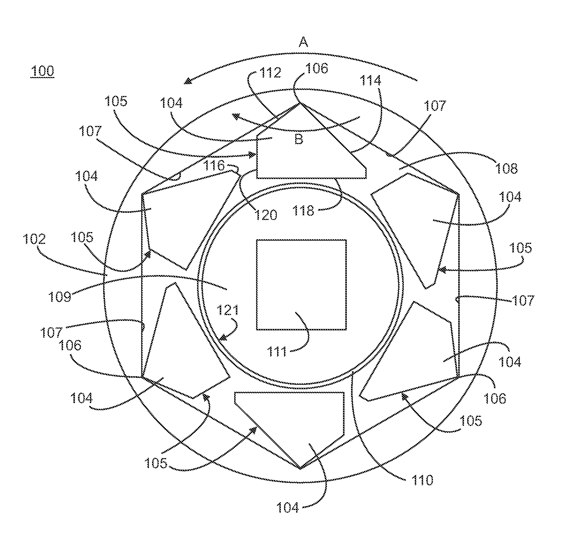
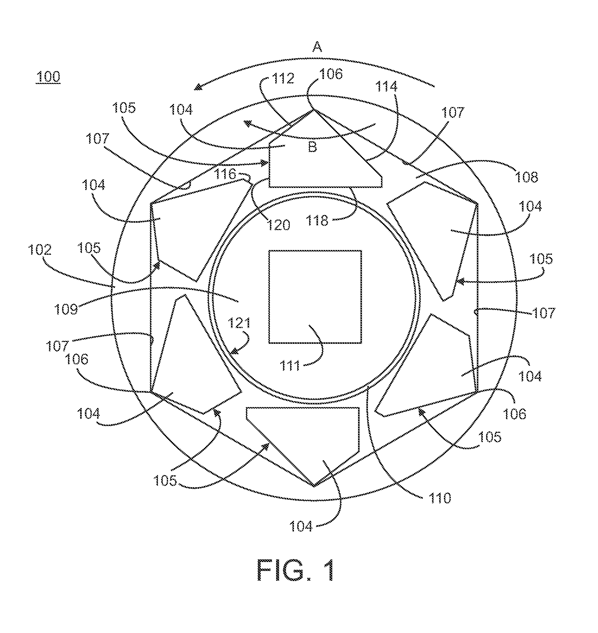
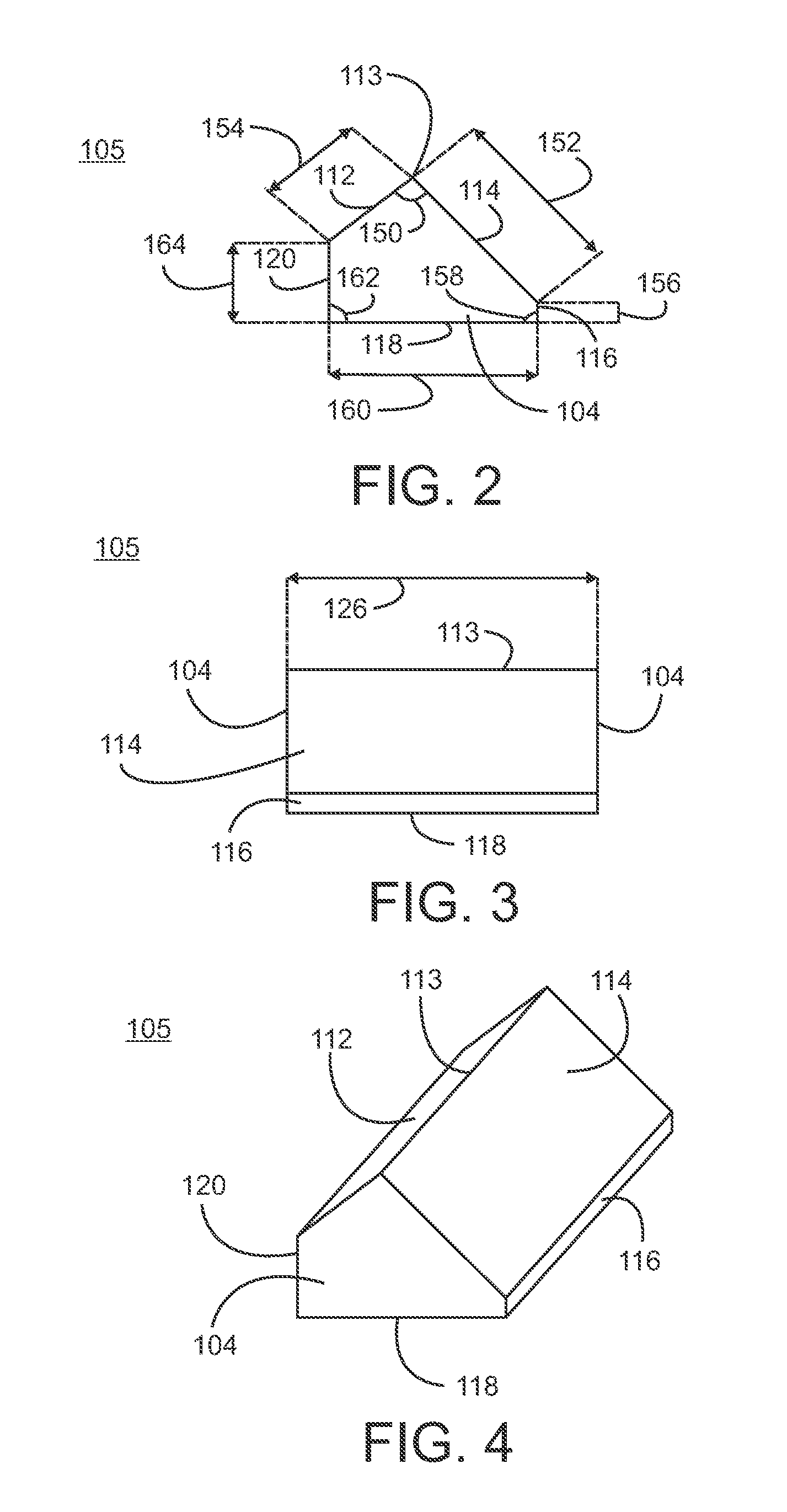
[0029]Referring initially to FIG. 1, an exemplary embodiment of a socket assembly 100 in accordance with the present invention is illustrated. In one embodiment, the socket assembly includes a plurality of multi-faceted segments 105. Although each multi-faceted segment can have a unique number, size and arrangement of facets, preferably, the plurality of multi-faceted segments contains a plurality of identical multi-faceted segments. For example, the plurality of multi-faceted segments includes six multi-faceted segments, and each multi-faceted segment has five flat facets, i.e., each facet is contained within a given plane and does not contain a curvature running along the facet between any two edges of the facet. In one embodiment, the plurality of multi-faceted segments is positioned in an annular arrangement with all facets extending parallel to each other.

[0030]In one embodiment, the socket assembly 100 includes a standard multi-point socket 102. Any suitable socket known and a...


PUM


Abstract

A socket assembly includes a plurality of multi-faceted segments disposed in a standard multi-point socket in an annular arrangement, one multi-faceted segment for each apex in the multi-point socket. Each multi-faceted segment has a length extending between two ends and a plurality of flat facets extending along the length including two outer facets defining a pivot edge that engages an apex between two internal socket walls and an internal facet facing inwardly and sized to engage a side of a multi-sided fastener. A retaining mechanism is provided to secure the plurality of multi-faceted segments in the standard multi-point socket.

Description

FIELD OF THE INVENTION[0001]The present invention relates to sockets used with socket wrenches.BACKGROUND OF THE INVENTION[0002]Socket wrenches typically include a plurality of sockets that are interchangeably attached to a wrench arm, for example, a ratchet arm. The plurality of sockets cover a range of standard and metric sizes and includes socket point shapes such as square, hexagon, octagon and double hexagon or dodecagon. The sizing fit between the socket size and the fastener, e.g., bolt, to be tightened or loosened is important, as stripping or rounding of the bolt head can result from a sizing mismatch. In addition, conventional sockets apply pressure on the corners of the bolt head. For bolt heads manufactured from softer metals, this enhances the risk or stripping or rounding. For painted bolts, epoxy coated bolts and chromed bolts, pressure applied to the corners of the bolts results in chipping or removal of the paints or coatings. As these paints and coatings are import...

Claims


Application Information

Patent Timeline
IPC IPC(8): B25B13/28B25B13/06B25B23/00
CPCB25B13/28B25B13/065B25B23/0007
Inventor CHRISTENSEN, ARTHUR E
Owner CHRISTENSEN ARTHUR E
Why Eureka
Try Eureka