
Fixed engine and rotating proprotor arrangement for a tiltrotor aircraft

a technology of fixed engine and rotating proprotor, which is applied in the direction of aircraft, vertical landing/take-off aircraft, vehicles, etc., can solve the problems of inability to perform maintenance on the rotating proprotor embedded in the wing structure, inability to perform maintenance on the rotating proprotor, and inability to achieve the operation of the aircra

Active Publication Date: 2015-11-03
BELL HELICOPTER TEXTRON INC
View PDF16 Cites 77 Cited by
  • Summary
  • Abstract
  • Description
  • Claims
  • Application Information

AI Technical Summary

Benefits of technology

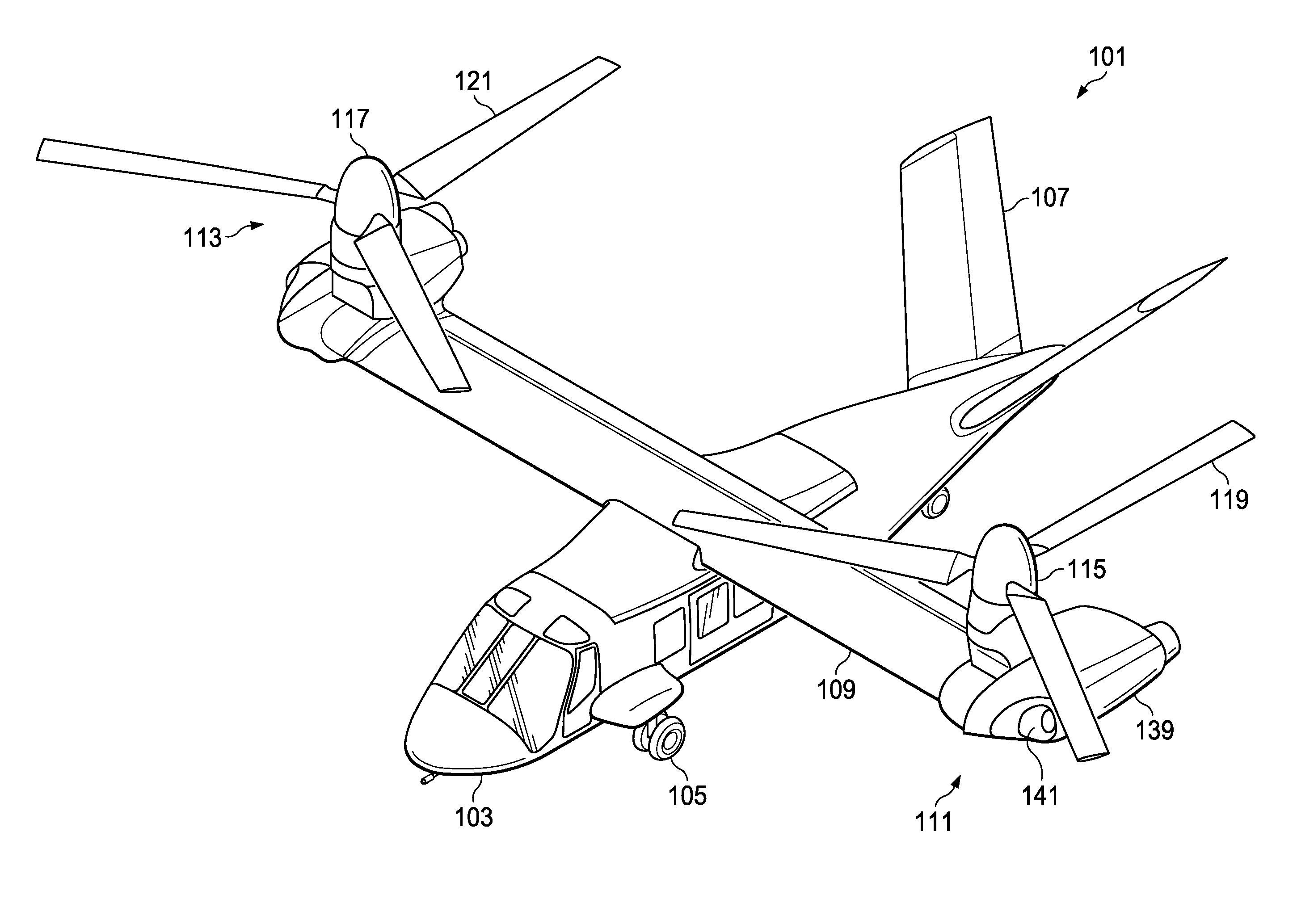
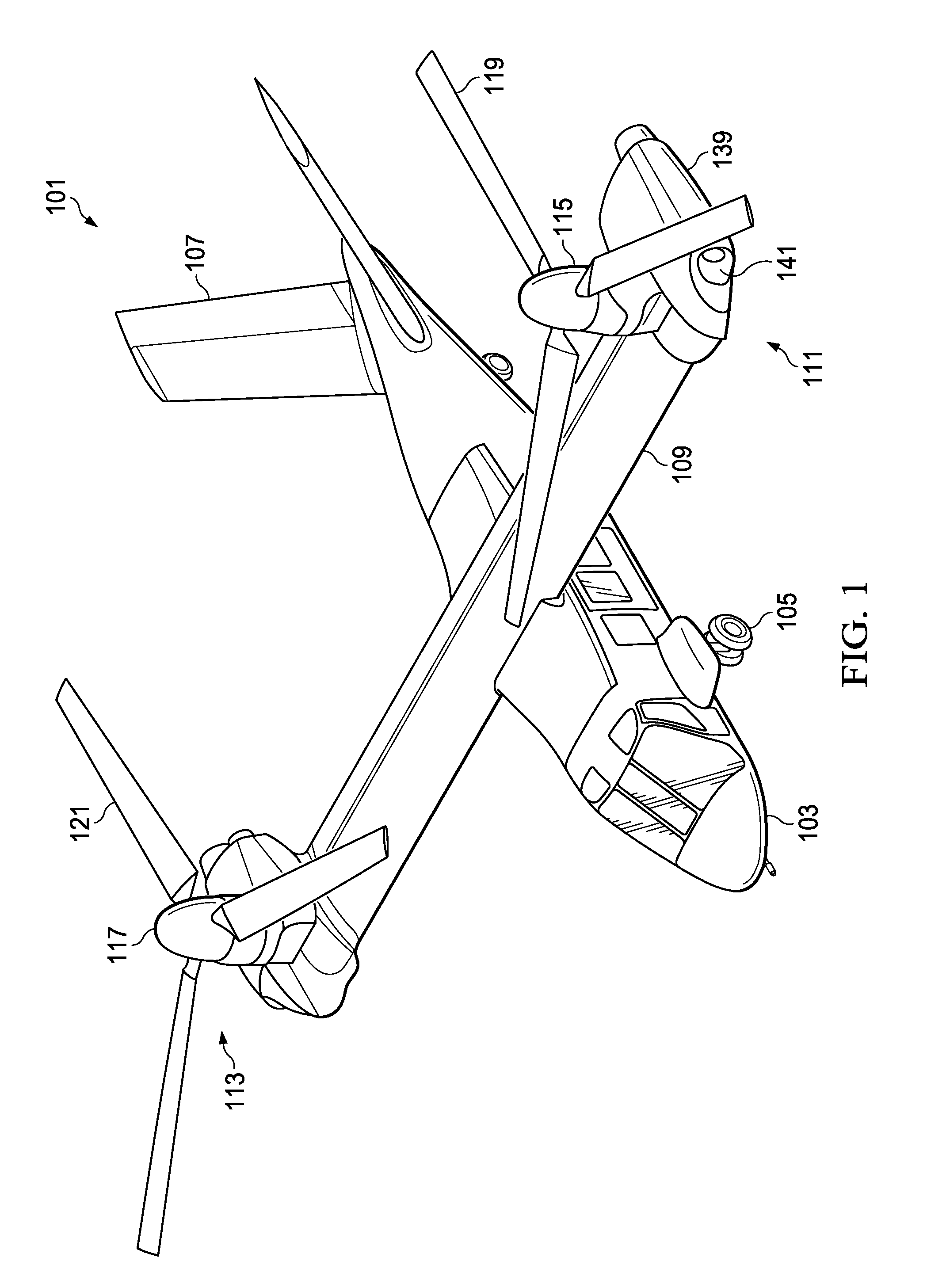
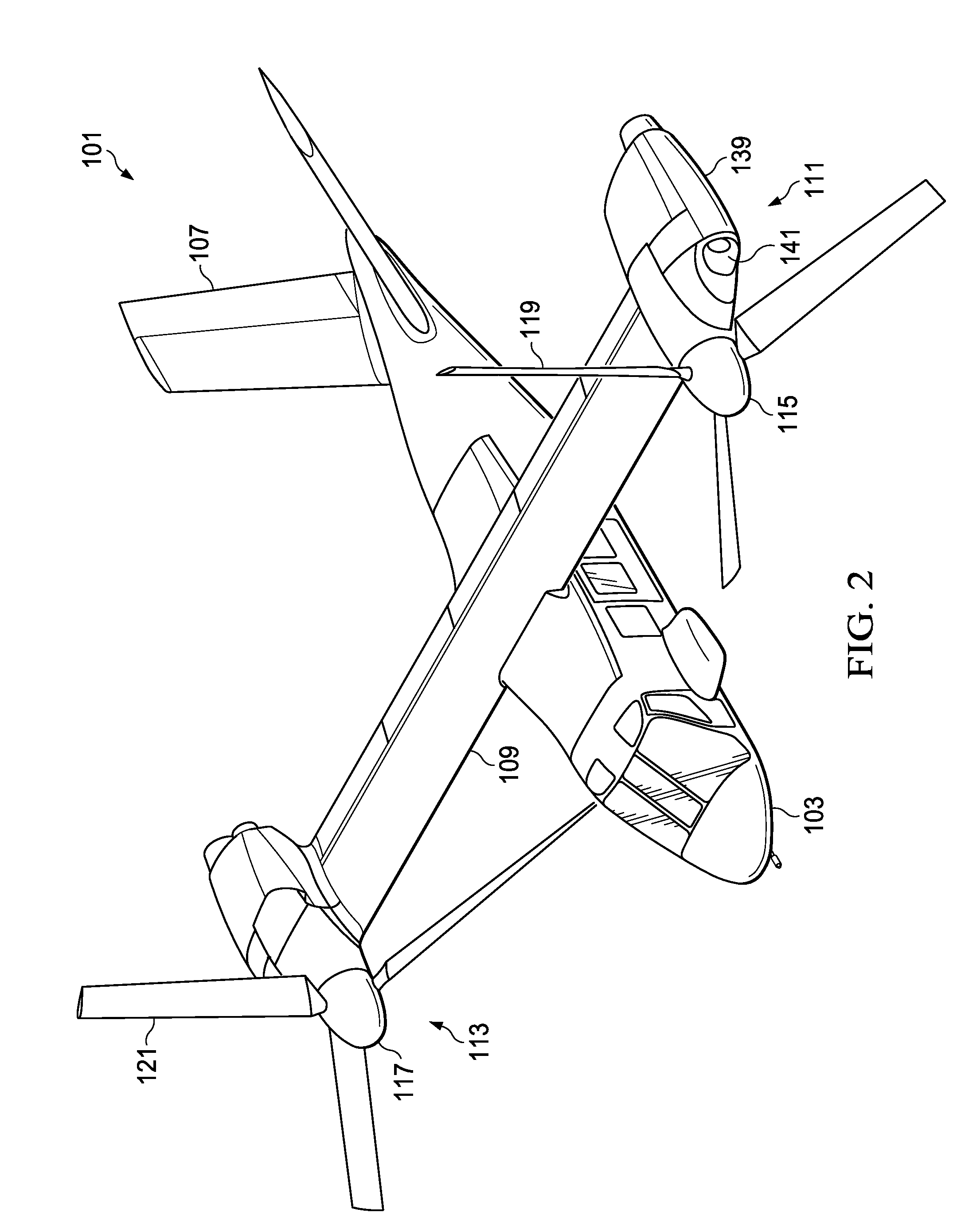
The present disclosure relates to a fixed engine and rotating proprotor arrangement for a tiltrotor aircraft. The technical effects of this arrangement include efficient use of structural mass, minimal misalignment between the fixed engine and rotating proprotor, and easy removability of the torque transferring shaft for maintenance and inspection. The method and apparatus also allow for misalignment between the two and provide a solution for the burdensome torque transferring shaft.

Problems solved by technology

Further, the location of the fixed engine and the rotating proprotor in relation to each other, as well as to the wing structure, can have significant influence upon the size and weight of the supporting structure, as well as the complexity of servicing procedures.
Further, a rotating proprotor embedded in the wing structure can be difficult and time-consuming to perform maintenance thereon.
During operation, the fixed engine and the rotating proprotor may each endure a different operational loading which can induce operational misalignment therebetween.
Also, misalignment can result from manufacturing and assembly tolerances.
Designing the aircraft with structure with sufficient strength to resist the operational and tolerance misalignment therebetween can be undesirable due to the weight thereof.
Further, conventional tiltrotor aircraft may have a torque transferring shaft between the fixed engine and the rotating proprotor that is burdensome to remove for maintenance and / or inspection, thus increasing the operational costs associated with operating the aircraft and performing maintenance and / or inspection thereof.

Method used


Image

  • Fixed engine and rotating proprotor arrangement for a tiltrotor aircraft
  • Fixed engine and rotating proprotor arrangement for a tiltrotor aircraft
  • Fixed engine and rotating proprotor arrangement for a tiltrotor aircraft

Examples


Embodiment Construction

[0023]Illustrative embodiments of the method and apparatus of the present disclosure are described below. In the interest of clarity, all features of an actual implementation may not be described in this specification. It will of course be appreciated that in the development of any such actual embodiment, numerous implementation-specific decisions must be made to achieve the developer's specific goals, such as compliance with system-related and business-related constraints, which will vary from one implementation to another. Moreover, it will be appreciated that such a development effort might be complex and time-consuming but would nevertheless be a routine undertaking for those of ordinary skill in the art having the benefit of this disclosure.

[0024]In the specification, reference may be made to the spatial relationships between various components and to the spatial orientation of various aspects of components as the devices are depicted in the attached drawings. However, as will ...


PUM


Abstract

A tiltrotor aircraft includes a fuselage; a wing member having a first rib, a second rib, a first spar, second spar; and an upper wing skin; an engine disposed at a fixed location relative to the wing member; and a proprotor having a spindle gearbox, rotor mast, and a plurality of rotor blades drivable in rotation about the rotor mast, the spindle gearbox being rotatable about a conversion axis. The spindle gearbox is located above the upper wing skin of the wing member.

Description

BACKGROUND[0001]1. Technical Field[0002]The present disclosure relates to a fixed engine and rotating proprotor arrangement for a tiltrotor aircraft. The present disclosure also relates to a method and apparatus of connecting a fixed drive system to a rotating drive system for a tiltrotor aircraft.[0003]2. Description of Related Art[0004]A conventional tiltrotor aircraft configuration can include a fixed engine with a rotating proprotor; however, conventional packaging arrangements of the fixed engine and the rotating proprotor can have significant shortcomings. Further, the location of the fixed engine and the rotating proprotor in relation to each other, as well as to the wing structure, can have significant influence upon the size and weight of the supporting structure, as well as the complexity of servicing procedures. For example, a rotating proprotor that is cantilevered outboard of the tip end of the wing can require significant structure to adequately support and prevent ope...

Claims


Application Information

Patent Timeline
Patent Type & Authority Patents(United States)
IPC IPC(8): B64C29/00
CPCB64C29/0033
Inventor ROSS, BRENT C.BOCKMILLER, DAVID R.MCCULLOUGH, JOHN R.CARLSON, DAVID G.
Owner BELL HELICOPTER TEXTRON INC
Learn More