
Two-stroke spark-ignition engine

a two-stroke, spark-ignition technology, applied in the direction of oscillatory slide valves, rotary slide valves, fuel systems, etc., can solve the problems of lower power output per liter and higher fuel consumption, and achieve the effect of reducing the penetration of combustion products

Active Publication Date: 2015-11-03
NOVOTNY ZDEN K
View PDF22 Cites 0 Cited by
  • Summary
  • Abstract
  • Description
  • Claims
  • Application Information

AI Technical Summary

Benefits of technology

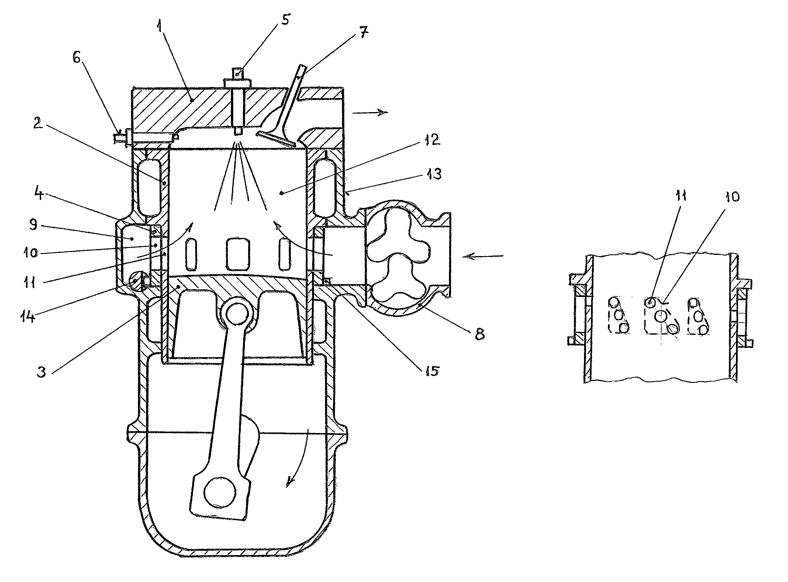
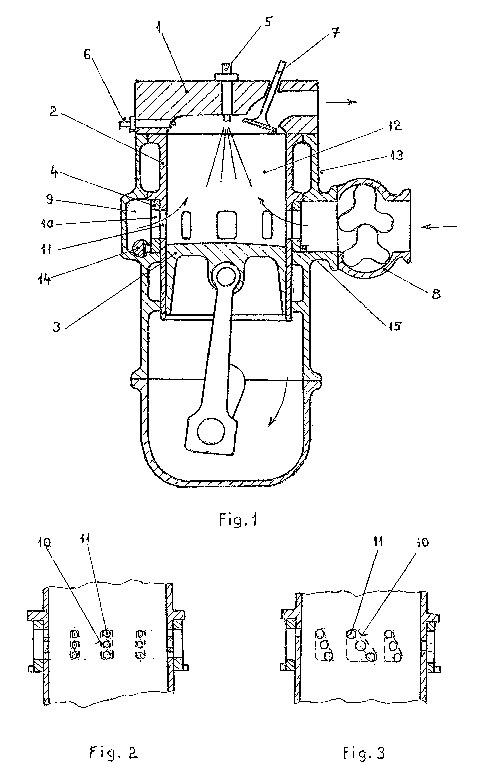
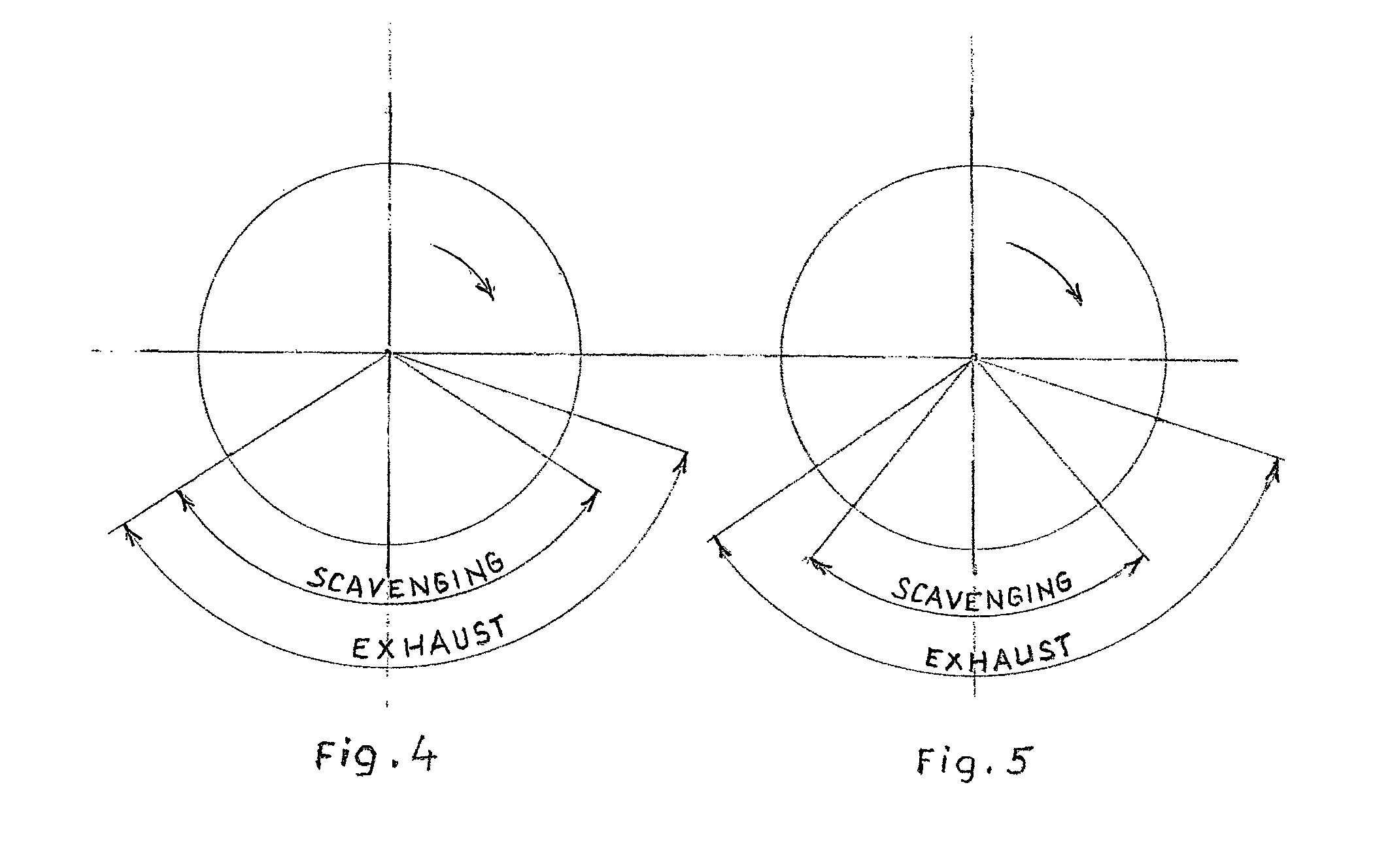
[0004]The principle of the invention is that the inlet air is throttled with a rotary bushing right at the inlet of the engine cylinder with the possibility of changing the timing of the start and end of air inlet into the engine cylinder and reduction of blowing of combustion products into the storage area filled by the charger or the engine crankcase. By the creation of sufficient pressure of fresh air before the cylinder entry with the use of a charger (i.e. a supercharger) or turbocharger the penetration of the combustion products is reduced even if the channels of the engine cylinder are fully open and filling of the cylinder with fresh air is improved. The injection of fuel through the fuel nozzle at the moment the engine piston has passed the bottom dead centre prevents fuel losses with the possibility to produce a stratified mixture with ignition consistency at the sparking plug in the cylinder head.

Problems solved by technology

A disadvantage of the current state of the art is imperfect scavenging of the cylinder with fresh air or a fresh mixture of air with fuel and low volume efficiency, which results in a lower power output per liter and higher fuel consumption.

Method used


Image

  • Two-stroke spark-ignition engine
  • Two-stroke spark-ignition engine
  • Two-stroke spark-ignition engine

Examples


Embodiment Construction

OF EMBODIMENT OF THE INVENTION

[0011]The two-stroke spark-ignition engine consists of the cylinder head 1 in which exhaust valves 7 are mounted in a sliding way and an injection nozzle 5 and sparking plug 6 is attached. In the cylinder block 13 a cylinder 2 is pressed in along the perimeter of which inlet openings 11 are created. In the cylinder 2 a piston 3 moves in a sliding way the movement of which is derived from the crank mechanism. In the space of the inlet openings 11 from the outside of the cylinder 2 a bushing 4 is mounted in a rotary way the perimeter of which contains throttle openings 10. In the bottom part of the bushing 4 there is a gear ring 15 that is firmly attached to it to the teeth, of which the teeth of a control rod 14 engage. The movement of the control rod 14 ensures rotary adjustment of the bushing 4. The control rod 14 is mounted in a sliding way in the cylinder block 13 and is controlled by the throttle pedal. In the cylinder block 13 an annular storage sp...


PUM


Abstract

A two-stroke spark-ignition engine with through scavenging, exhaust valves (7), an injection nozzle (5) and sparking plug (6) in the cylinder head is characterized by higher volume efficiency and higher volume output with the possibility of gradual change of timing of air inlet into the engine cylinder (2) from the idle run to the full power. The use of a charger or turbocharger is convenient. Higher volume efficiency is achieved by a limitation of flow of exhaust gas back to the suction part through a gradual change of the inlet section to the engine cylinder (2) and by ensuring a higher air pressure before the inlet section. The change of the inlet section is achieved by a rotary bushing (4) on the cylinder (2) or insert of the engine cylinder (2), the bushing (4) being controlled with a control rod (14) from the throttle pedal.

Description

[0001]This is a national stage application under 35 U.S.C. §371 of International Application PCT / CZ2011 / 000121 filed 22 Dec. 2011, which claims the benefit of Czech Republic application Serial No. PV 2011-104 filed 28 Feb. 2011, the entire disclosures of which are incorporated herein by reference.FIELD OF THE INVENTION[0002]The invention deals with a two-stroke spark-ignition engine for use in a car, motorbike, sports or tourist aircraft or as the drive of industrial units.BACKGROUND OF THE INVENTION[0003]In existing two-stroke spark-ignition engines the engine cylinder is filled via the crankcase with throttling of inlet air by a throttle valve in the suction pipeline or carburettor. A disadvantage of the current state of the art is imperfect scavenging of the cylinder with fresh air or a fresh mixture of air with fuel and low volume efficiency, which results in a lower power output per liter and higher fuel consumption.SUMMARY OF THE INVENTION[0004]The principle of the invention i...

Claims


Application Information

Patent Timeline
Patent Type & Authority Patents(United States)
IPC IPC(8): F02B15/00F02B21/00F02B75/02F02B1/10F01L7/12F01L7/04F02F1/22F02B3/00F02B25/00F02B1/04F02F1/42
CPCF02F1/22F01L7/04F01L7/12F02B1/10F02B21/00F02B75/02F02B1/04F02B2075/025F02B2720/136F02F1/4214
Inventor NOVOTNY, ZDENEK
Owner NOVOTNY ZDEN K
Learn More