ERV global pressure demand control ventilation mode

a global pressure demand and ventilation mode technology, applied in ventilation systems, lighting and heating apparatus, heating types, etc., can solve the problem of significant potential energy loss from air exchang

Active Publication Date: 2015-11-03
LENNOX IND
View PDF106 Cites 14 Cited by
  • Summary
  • Abstract
  • Description
  • Claims
  • Application Information

AI Technical Summary

Problems solved by technology

This exchange of air is a significant potential source of energy loss, as fresh air may need to be cooled or heated to maintain the temperature set point in the building, and previously cooled or heated air is lost to the environment.

Method used


Image

  • ERV global pressure demand control ventilation mode
  • ERV global pressure demand control ventilation mode
  • ERV global pressure demand control ventilation mode

Examples


Embodiment Construction

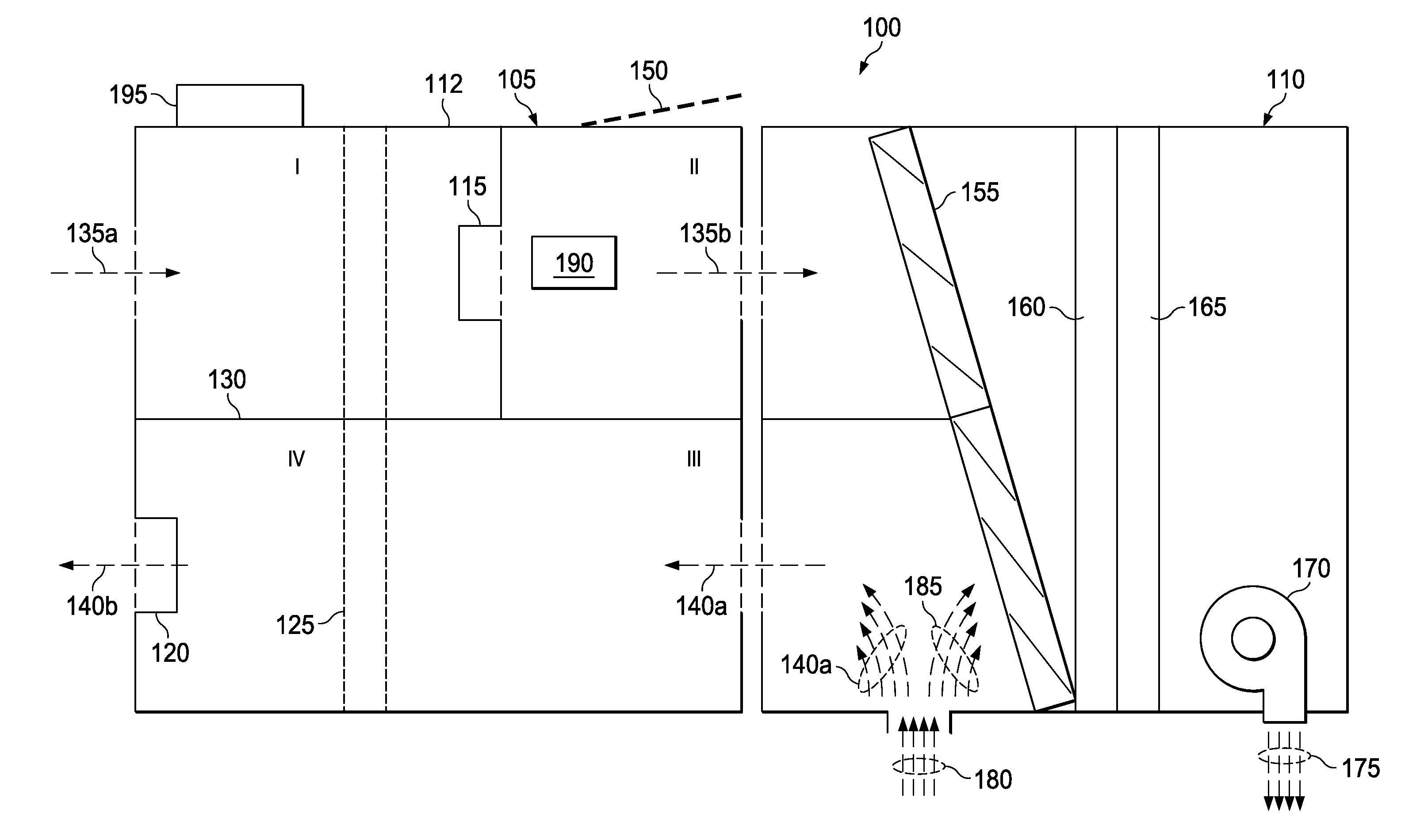
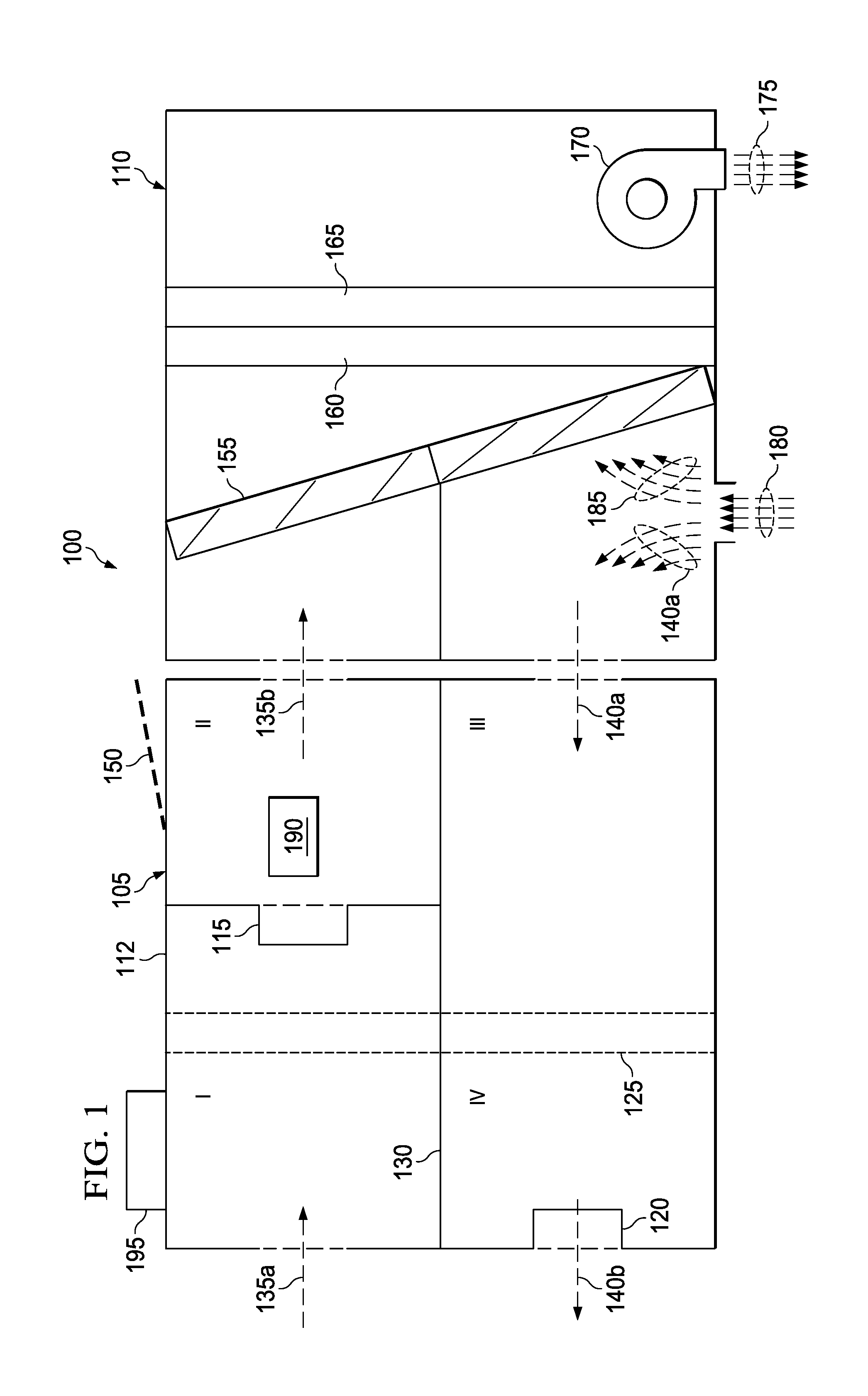
[0015]Many commercial buildings provide heating and cooling with a roof-top heating, ventilating and air conditioning (HVAC) unit, or RTU. Some such systems include an air-side economizer, or briefly, an economizer. The economizer provides the ability to selectively provide fresh outside air to the RTU or to recirculate exhaust air from the building back through the RTU to be cooled or heated again.

[0016]The HVAC system typically recirculates a portion of the exhaust air as it heats or cools the air. When the enthalpy of the fresh air is less than the enthalpy of the recirculated air, conditioning the fresh air may be more energy-efficient than conditioning the recirculated air. In this case the economizer may exhaust a portion of the stale air and replace the vented air with outside air. When the outside air is both sufficiently cool and sufficiently dry it may be possible that no additional conditioning of the outside air is needed. In this case the economizer may draw a sufficien...


PUM


Abstract

An energy recovery ventilator includes first and second blowers, a pressure transducer and a controller. The first blower is configured to direct a first air stream into a first zone of an enclosure. A second blower configured to direct a second air stream into a second zone of the enclosure. A pressure transducer is configured to determine internal air pressure within the enclosure. A controller is configured to control the first blower and / or the second blower in response to the internal air pressure.

Description

CROSS-REFERENCE TO RELATED APPLICATION[0001]This application is related to U.S. application Ser. No. 13 / 267,542 to Justin McKie, et al. and U.S. application Ser. No. 13 / 267,441 to Justin McKie, et al. both filed on even date herewith, and both commonly assigned with this application and incorporated herein by reference.TECHNICAL FIELD[0002]This application is directed, in general, to climate control systems, and, more specifically, to methods and systems for improving operating efficiency of such system.BACKGROUND[0003]Some HVAC units are located on the rooftop of a commercial building. These so-called rooftop units, or RTUs, typically include one or more blowers and heat exchangers to heat and / or cool the building, and baffles to control the flow of air within the RTU.[0004]One aspect of airflow control is the venting of stale air within the building and the intake of fresh air from the outside to maintain air quality within the building. This exchange of air is a significant poten...

Claims


Application Information

Patent Timeline
Patent Type & Authority Patents(United States)
IPC IPC(8): F24F7/06F24F11/02F24F7/007F24F11/00F24F12/00
CPCF24F11/0079F24F12/001F24F2011/0042F24F2203/10Y02B30/563Y02B30/746F24F11/77F24F2110/40Y02B30/56Y02B30/70F24F11/0001F24F2011/0002B23P19/00
Inventor MCKIE, JUSTINPEREZ, ERICSCHNEIDER, STEVE
Owner LENNOX IND
Why Eureka
Try Eureka