Image intensifier having an ion barrier with conductive material and method for making the same

an image intensifier and conductive material technology, applied in the direction of cathode ray tubes/electron beam tubes, electron multiplier details, electric discharge tubes, etc., can solve the problem of brightness loss of the image intensifier tubes

Active Publication Date: 2015-11-03
ELBIT SYSTEMS OF AMERICA LLC
View PDF19 Cites 6 Cited by
  • Summary
  • Abstract
  • Description
  • Claims
  • Application Information

AI Technical Summary

Benefits of technology

The present invention offers an improved image intensifier tube with a collider and a microreceiving channel plate that work together effectively without interference. A thin membrane made up of conductive materials helps reduce electron loss during transmission through the device. This results in higher quality images captured by the tube.

Problems solved by technology

The technical problem addressed in this patent is the halo effect, which refers to the scattering of electrons in an image intensifier tube and the resulting brightness loss. The patent aims to reduce the halo effect and produce an image intensifier tube with reduced secondary emissions, reduced halo in the output image, and reduced charge build-up that causes image burn-in and may damage the image intensifier tube.

Method used


Image

  • Image intensifier having an ion barrier with conductive material and method for making the same
  • Image intensifier having an ion barrier with conductive material and method for making the same
  • Image intensifier having an ion barrier with conductive material and method for making the same

Examples


Embodiment Construction

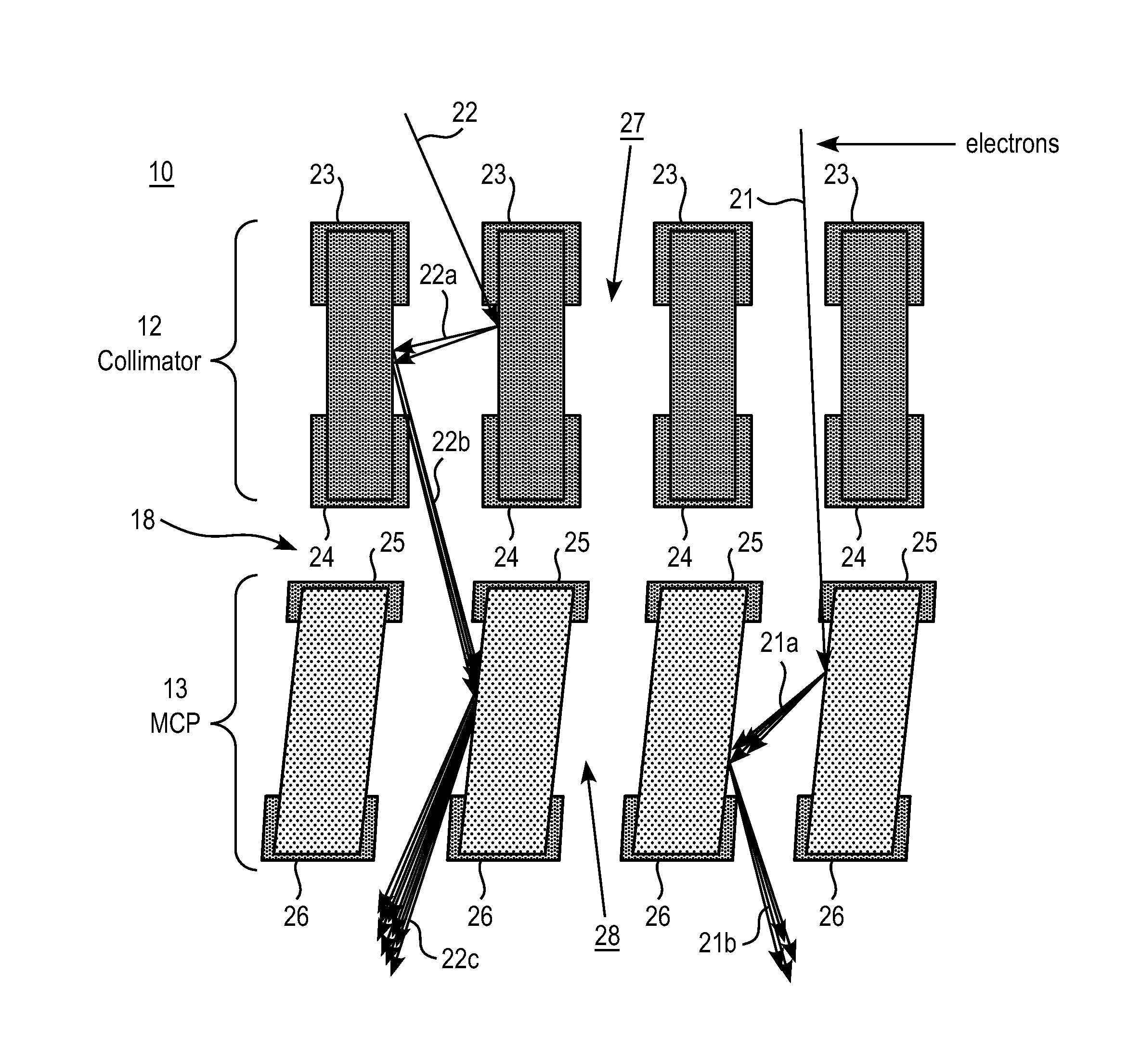
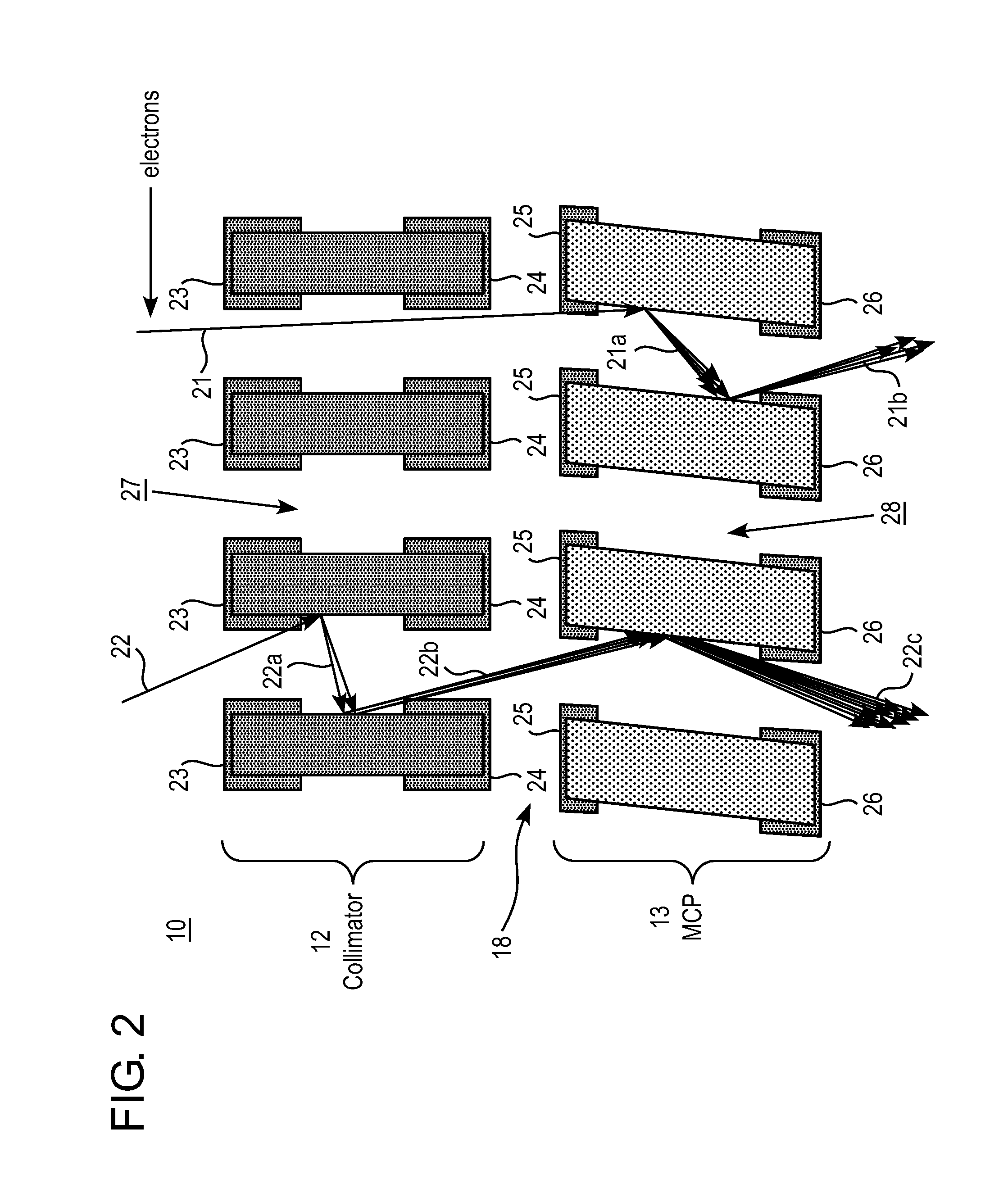
[0018]The present invention provides an image intensifier tube including a photocathode at an input side, and a phosphor screen at an output side; in addition, a collimator and an MCP are inserted between the photocathode and the phosphor screen. The collimator is positioned following the photocathode; and the MCP is positioned following the photocathode and in front of the phosphor screen. Moreover, the input side of the MCP includes an ion barrier film (IBF) which has a small amount of conductive material such as chromium oxide.

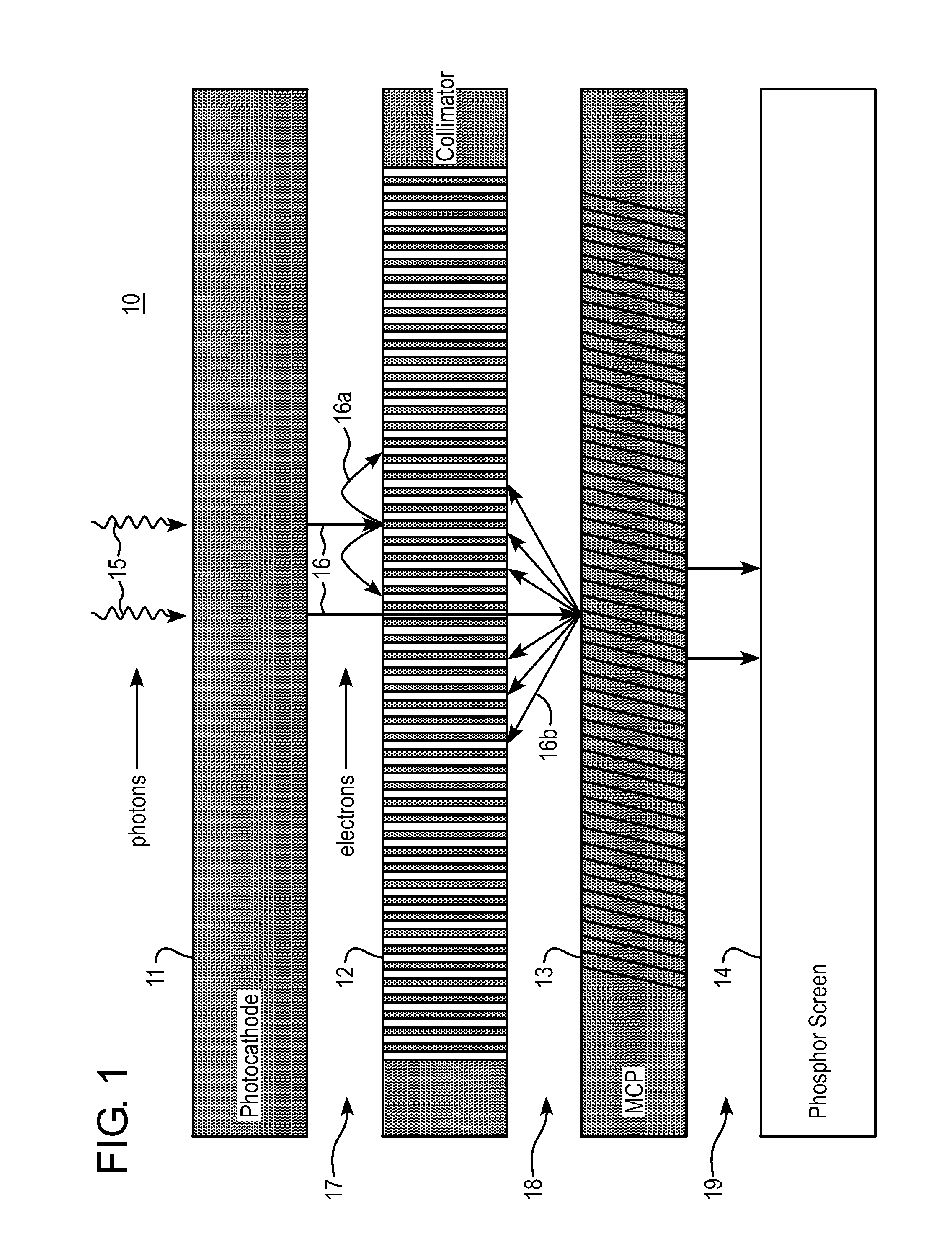
[0019]Referring first to FIG. 1, an image intensifier tube, generally designated as 10, includes, in spatial sequence, photocathode 11, collimator 12, MCP 13 and phosphor screen 14. Photons 15 enter at the top of FIG. 1, penetrate a faceplate (not shown) and strike photocathode 11. Some of the photons 15 react with the photocathode to liberate electrons 16, which enter a vacuum space (gap) 17 between photocathode 11 and collimator 12. The electrons are acce...


PUM


Abstract

An image intensifier tube includes a collimator having multiple channels for receiving electrons from a photocathode layer, and a microchannel plate (MCP) having multiple channels for receiving electrons from the collimator. An ion barrier film (IBF) is disposed on top of an input side of the MCP, in which the IBF includes a small amount of conductive material. The IBF may include alumina doped with chromium oxide, or manganese oxide, or any other conductive material. The small amount of conductive material includes 1% to 5% of conductive material in a layer of non-conductive material.

Description


Claims


Application Information

Patent Timeline
Owner ELBIT SYSTEMS OF AMERICA LLC
Why Eureka
Try Eureka