Recording apparatus

a recording head and taper technology, applied in the direction of printing, other printing apparatus, etc., can solve the problems of deformation of the fastening state of the vis, uneven gap between the platen and the recording head, and deformation of the recording quality on the recording medium, etc., to achieve the effect of reducing rigidity

Active Publication Date: 2015-11-10
SEIKO EPSON CORP
View PDF9 Cites 4 Cited by
  • Summary
  • Abstract
  • Description
  • Claims
  • Application Information

AI Technical Summary

Benefits of technology

[0013]An advantage of some aspects of the invention is to provide a recording apparatus that can suppress degradation of recording quality on a recording medium and reduce occurrence of failure in transporting the recording medium by reducing deformation of a medium support member.
[0014]According to an aspect of the invention, there is provided a recording apparatus including a recording head that performs recording on a recording medium, a medium support member that is disposed at a position where the medium support member can face the recording head and supports the recording medium, and a reinforcing member that is attached below the medium support member and has a greater rigidity than the medium support member, in which the medium support member has bendability to follow the reinforcing member in a direction intersecting a transport direction of the recording medium, and the medium support member includes a rigidity reduction unit that reduces the rigidity of the medium support member in a direction intersecting a transport direction of the recording medium.
[0015]In this case, the medium support member that supports the recording medium is attached to the reinforcing member that has a greater rigidity than the medium support member and has bendability to follow the reinforcing member in the direction intersecting the transport direction of the recording medium. Accordingly, the medium support member follows the reinforcing member in the intersecting direction even when the medium support member bends due to change in volume caused by environmental change such as temperature and humidity. Thus, the medium support member is dependent on the accuracy of the reinforcing member. Consequently, deformation of the medium support member can be suppressed on the transport path of the recording medium. Therefore, degradation of recording quality on the recording medium can be suppressed, and occurrence of failure in transporting the recording medium can be reduced. In addition, the medium support member includes a rigidity reduction unit that reduces the rigidity of the medium support member in the direction intersecting the transport direction of the recording medium. Accordingly, the medium support member follows the reinforcing member attached to the medium support member even when the medium support member bends due to change in volume caused by environmental change such as humidity since the rigidity reduction unit allows the rigidity of the medium support member to be smaller than that of the reinforcing member. Consequently, the medium support member is dependent on the accuracy of the reinforcing member, and the amount of deformation of the medium support member can be reduced. Therefore, degradation of recording quality on the recording medium can be suppressed, and occurrence of failure in transporting the recording medium can be reduced on the transport path of the recording medium.

Problems solved by technology

Accordingly, in the recording apparatus disclosed in JP-A-2012-25082, even adjusting the fastening state of the vis may not be able to resolve deformation of the platen when the platen is deformed more than expected.
As a consequence, a gap between the platen and the recording head may not be uniform in the direction intersecting the transport direction of the recording medium.
Therefore, recording quality on the recording medium may be degraded, and failure may occur in transporting the recording medium.
Therefore, deformation of the platen cannot be reduced.
As a consequence, deformation of the platen may cause failure to occur in transporting the recording medium.

Method used


Image

  • Recording apparatus
  • Recording apparatus
  • Recording apparatus

Examples


first embodiment

Regarding First Embodiment

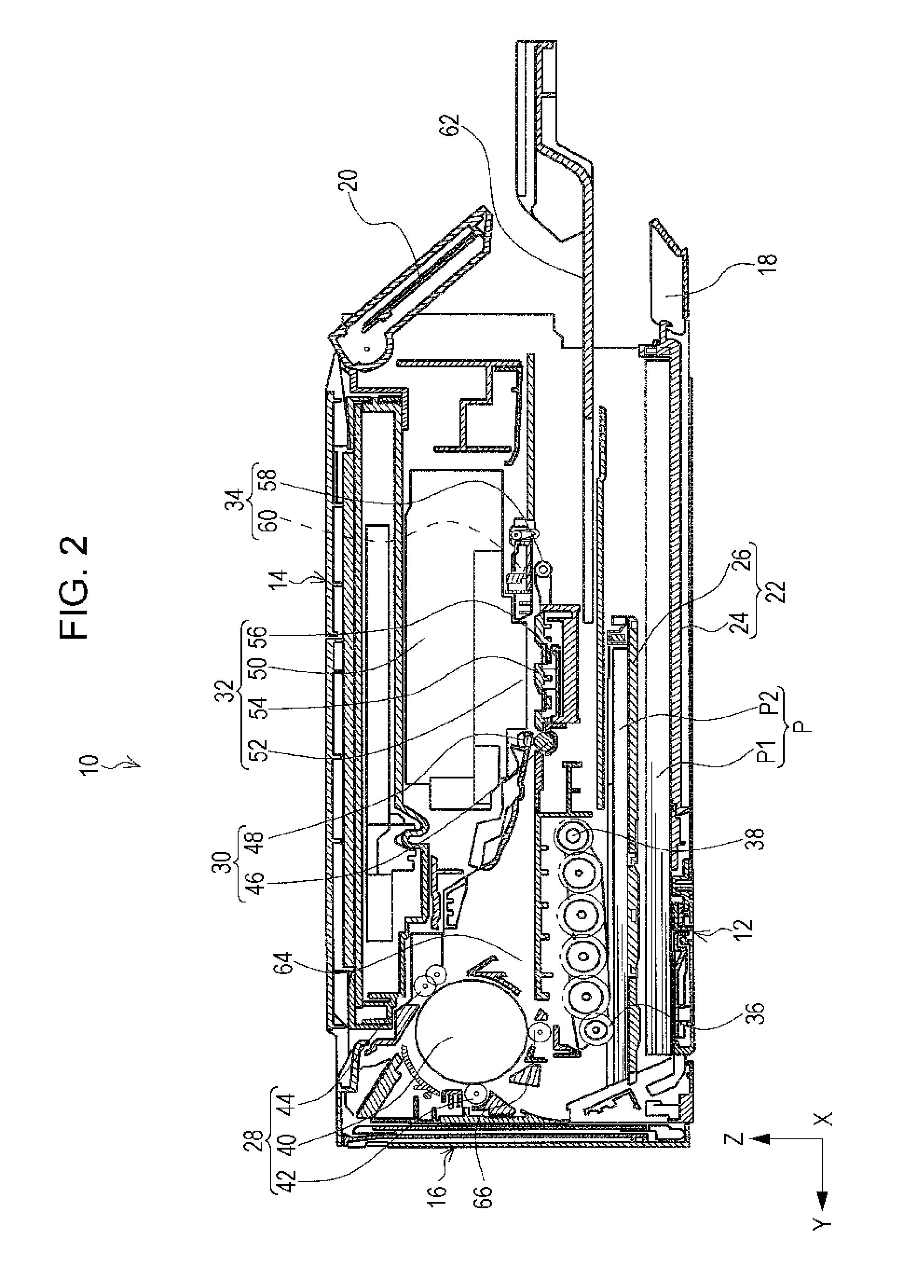
[0065]The platen 54 will be described with reference to FIG. 3 to FIG. 8B. With reference to FIG. 3, the platen 54 is positioned below the carriage 50 in the apparatus main body 12 and is disposed so as to face the recording head 52 in an area where the carriage 50 is movable. The apparatus main body 12 includes a pair of frames 68 and 68 that is arranged at an interval in the X axis direction as illustrated in FIG. 3. In the present embodiment, both end portions of the platen 54 in the X axis direction are supported by the frames 68 and 68 (refer to FIG. 4).

[0066]A plurality of ribs 70 stands on the side of the platen 54, that is, on an upper surface 54a facing the recording head 52. The plurality of ribs 70 supports the paper P when the paper P is transported to the platen 54. The ribs 70 are plurally (70a, 70b, and 70c) arranged along the Y axis direction, that is, the transport direction of the paper P as illustrated in FIG. 4. In addition, the ribs 70a...

modification example of first embodiment

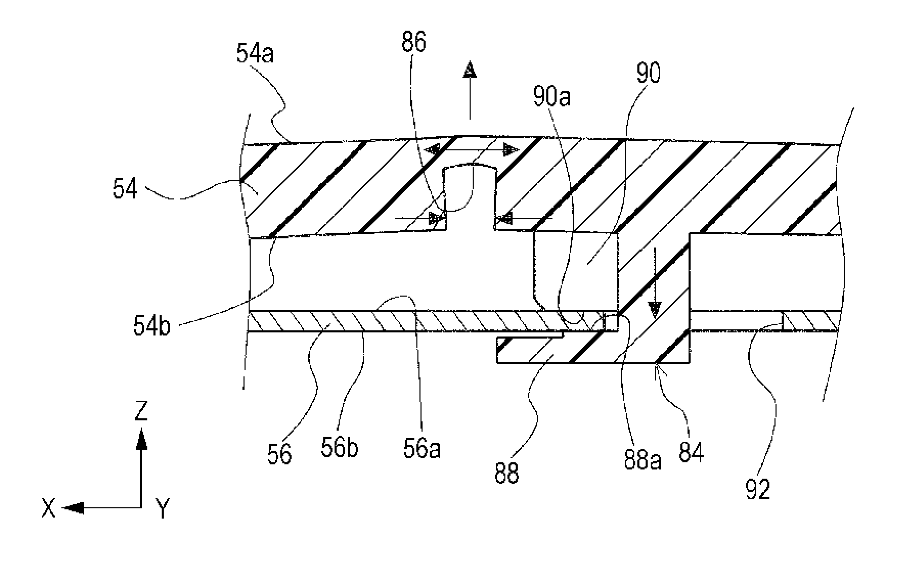
[0092](1) The groove 86 may be configured to be disposed on the upper surface 54a as illustrated in FIG. 10A instead of the configuration in which the groove 86 is disposed on the lower surface 54b of the platen 54 in the present embodiment.

[0093]According to this configuration, the central portion of the platen 54 in the X axis direction bends in a direction separating from the recording head 52, that is, in the −Z axis direction when the platen 54 expands in response to humidity change since the groove 86 is disposed on the upper surface 54a of the platen 54. As a consequence, the gap PG between the recording head 52 and the platen 54 becomes great. Thus, occurrence of wear of the head caused by contact between the recording head 52 and the paper P can be reduced.

[0094](2) The groove 86 may be configured to be alternately disposed on the upper surface 54a and the lower surface 54b as illustrated in FIG. 10B instead of the configuration in which the groove 86 is disposed on the low...


PUM


Abstract

A recording apparatus includes a recording head that performs recording on a recording medium, a medium support member that is disposed at a position where the medium support member can face the recording head and supports the recording medium, and a reinforcing member that is attached below the medium support member and has a greater rigidity than the medium support member. The medium support member includes a rigidity reduction unit that reduces the rigidity of the medium support member in a direction intersecting a transport direction of the recording medium.

Description

BACKGROUND[0001]1. Technical Field[0002]The present invention relates to a recording apparatus that performs recording on a recording medium.[0003]In the present application, types of the recording apparatus include a serial printer that performs recording while a recording head moves in a predetermined direction; a line printer in which a recording head does not move; and a copy machine, a facsimile, and the like that have functions of the above printers.[0004]2. Related Art[0005]A recording apparatus that includes a medium support unit and a base body unit is widely used in the related art (JP-A-2012-25082). The medium support unit supports a recording medium in an area where recording is performed by a recording head. The base body unit supports both end portions of the medium support unit in a direction intersecting the transport direction of the recording medium.[0006]The medium support unit (hereinafter, referred to as “platen”) is attached to the base body unit (hereinafter, ...

Claims


Application Information

Patent Timeline
Patent Type & Authority Patents(United States)
IPC IPC(8): B41J11/02B41J11/00
CPCB41J11/02B41J11/0085B41J11/0065B41J11/06
Inventor YOSHINO, SATOSHITAMAI, KENSUKE
Owner SEIKO EPSON CORP
Why Eureka
Try Eureka